
Introduction
Continuous Casting Machine (CCM) technology is a fundamental part of modern steel production. It converts molten steel into semi-finished products such as billets, blooms, slabs and rounds through a continuous and controlled solidification process.
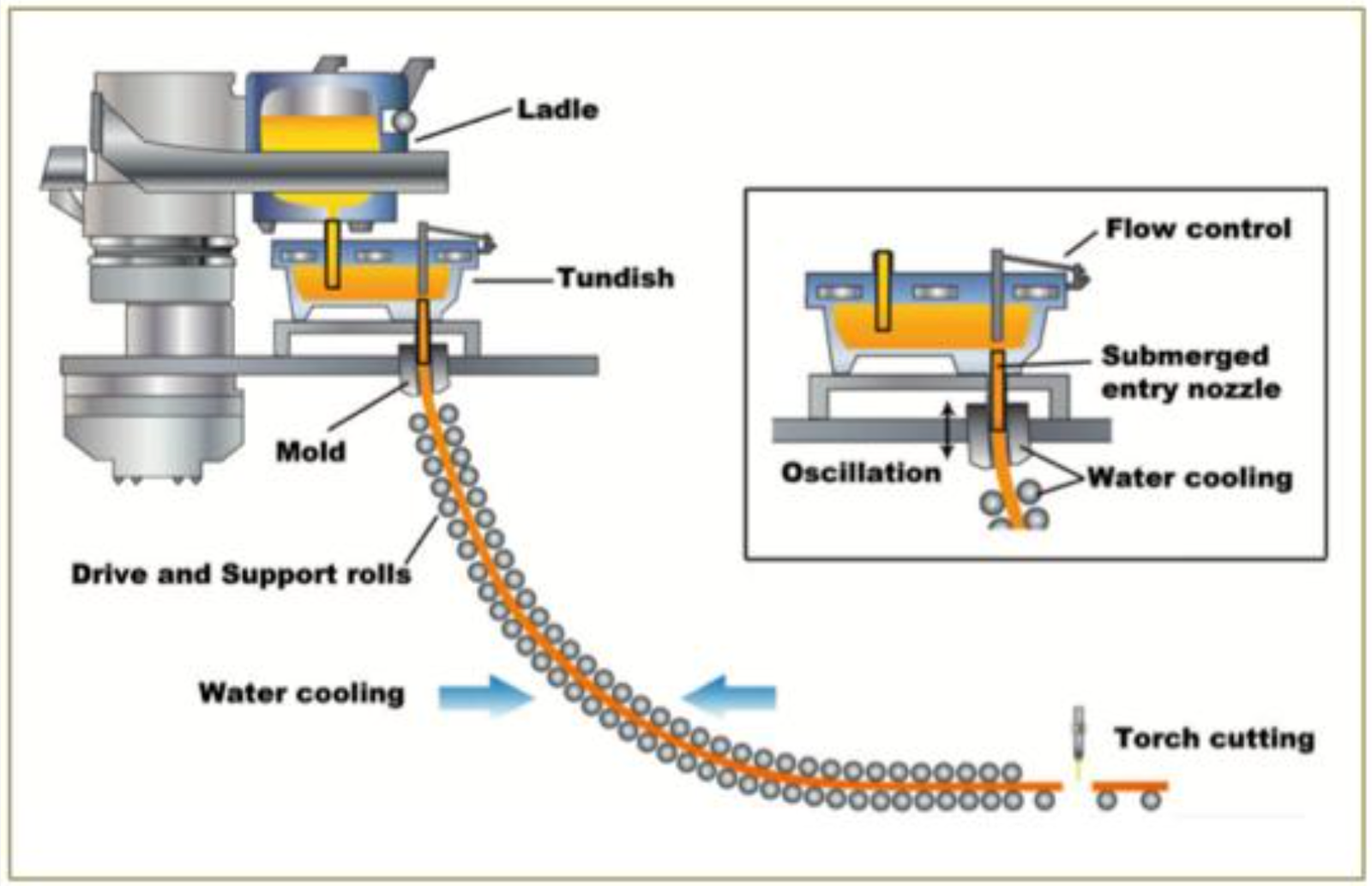
Unlike conventional ingot casting, continuous casting allows liquid steel to be fed continuously into a water-cooled mould while the partially solidified strand is withdrawn at a controlled speed. The strand continues to cool as it passes through the secondary-cooling and support zones, after which it is cut into the required lengths.
For steel plants, a well-operated CCM can improve production productivity, material yield, dimensional consistency and integration with downstream rolling mills. However, these benefits depend on careful control of casting temperature, mould condition, tundish performance, casting speed, cooling-water distribution and equipment reliability.
This guide covers the main components of a billet CCM, preparation before casting, tundish preparation, the operating sequence, critical process parameters, common defects and essential safety practices.
1. What Is Continuous Casting?
Continuous casting is a process in which molten steel is solidified into a continuous strand and cut into semi-finished products of the required length.
The process typically follows this sequence:
Steel ladle → Tundish → Water-cooled mould → Secondary cooling → Strand withdrawal and support → Cutting → Billet handling
Main advantages of continuous casting
Continuous production of billets, blooms, slabs or other designed sections.
Improved integration between steelmaking and rolling.
Reduced need for separate ingot casting and primary breakdown operations.
Better control over product dimensions and solidification conditions.
Potential improvements in material yield and production efficiency.
Easier heat and product traceability when supported by effective process records.
Continuous casting does not automatically eliminate porosity, segregation, cracks or inclusions. These defects must be controlled through suitable steel quality, casting practice, thermal management and equipment maintenance.
2. Main Components of a Continuous Casting Machine
A CCM consists of several interconnected systems. The exact arrangement depends on the machine design, number of strands and product section.
2.1 Steel ladle
The ladle receives liquid steel from the steelmaking or refining process and transfers it to the caster. It must be correctly prepared, refractory-lined and suitable for the heat before casting begins.
2.2 Ladle turret and ladle control system
The turret supports and positions the ladle above the tundish. Depending on the machine, the ladle may discharge through a slide gate or another controlled outlet.
The system must allow safe positioning and controlled steel flow, with emergency provisions as required by the caster design.
2.3 Tundish
The tundish is an intermediate refractory-lined vessel between the ladle and mould.
Its functions include:
Providing a controlled reservoir of liquid steel.
Distributing steel to one or more strands.
Supporting stable mould-level control.
Providing residence time for some inclusions to separate, depending on flow conditions.
Helping regulate steel flow through the tundish outlet system.
Tundish performance depends on its geometry, refractory condition, flow-control arrangement, steel level and operating practice.
2.4 Tundish nozzle and stopper system
The nozzle provides a controlled passage for steel from the tundish to the mould. A stopper rod, slide gate or other system may regulate the flow, depending on the design.
The system must be checked for damage, blockage, alignment and correct operation before casting.
2.5 Mould
The mould is usually made from a water-cooled copper component designed for the product section. It removes heat from the liquid steel and forms the initial solid shell.
The shell must become sufficiently strong to contain the liquid core as the strand leaves the mould. Mould condition, cooling-water performance, alignment, oscillation and lubrication are important to stable casting.
2.6 Mould oscillation system
The oscillation system moves the mould according to a defined pattern. Together with the appropriate mould lubricant or casting powder, it helps manage friction and shell formation.
Oscillation settings must be compatible with the casting speed, steel grade, mould design and process recipe.
2.7 Secondary cooling system
Below the mould, the strand passes through spray or air-mist cooling zones. These zones remove additional heat and support progressive solidification.
Cooling intensity must be appropriate for the grade, section, casting speed and machine layout. Uneven or unsuitable cooling can contribute to surface and internal cracking. [2][3]
2.8 Withdrawal and strand-support system
Withdrawal rolls extract the strand at the specified speed. Support rolls guide the partially solidified strand and help maintain its shape.
The roll system must be aligned, maintained and operated within the machine's design limits.
2.9 Cutting system
The cutting system divides the strand into the required lengths. Steel billet casters commonly use an oxy-fuel cutting torch or another machine-specific cutting arrangement.
The cutting system must be synchronised with strand movement and the specified product length.
2.10 Automation and safety systems
Depending on the caster, these may include:
Mould-level measurement and control.
Casting-speed control.
Mould and secondary-cooling water monitoring.
Temperature and process-data recording.
Breakout detection.
Emergency stops and interlocks.
Cutting-length control.
Alarm and event logging.
These systems support stable operation but do not replace operator training, inspections or the approved emergency procedure.
3. CCM Preparation Before Starting Casting
A systematic pre-start inspection helps reduce equipment failures, casting interruptions and quality problems.
Step 1 — Inspection and maintenance
Inspect the CCM and its supporting equipment according to the maintenance checklist.
Check:
Mould condition, wear and alignment.
Withdrawal rolls, guide rolls and drive systems.
Oscillation mechanism and associated controls.
Cutting equipment and its movement.
Tundish support and positioning equipment.
Cooling-water circuits, pumps, valves and spray nozzles.
Instrumentation, interlocks and emergency stops.
Fume extraction and working-platform condition.
Any defect that affects safe operation or product quality must be addressed before the caster is released.
Step 2 — Cleaning and housekeeping
Remove accumulated scale, debris and other contamination from accessible equipment areas using approved methods.
Keep the strand path, maintenance platforms and access routes clear. Cleaning must not introduce water into hot equipment or near molten steel.
Step 3 — Lubrication
Lubricate designated bearings, roll drives, moving mechanisms and other service points according to the manufacturer's lubrication chart.
Do not apply general-purpose lubricant indiscriminately to the mould. Mould lubrication for steel casting is provided by the casting powder or oil system specified for that caster and steel grade.
Step 4 — Set the casting recipe
Confirm the approved process recipe for the steel grade and product section.
The recipe may define:
Casting speed.
Steel temperature or superheat target.
Mould-level operating range.
Mould oscillation settings.
Mould cooling-water requirements.
Secondary-cooling settings.
Tundish steel-level targets.
Cutting length and cutting sequence.
Use the plant's validated settings rather than generic values from another caster.
Step 5 — Inspect and prepare the mould
Check the mould's condition, cooling passages, assembly, alignment and relevant monitoring systems.
Confirm that the mould is installed correctly and that its cooling system is operating within the required limits. Mould preheating, if specified, must follow the equipment manufacturer's procedure.
Step 6 — Check the cooling systems
Verify the required cooling-water flow, pressure, temperature and alarms for the mould and secondary-cooling systems.
Inspect spray nozzles and headers for blockage, leakage, incorrect alignment or abnormal flow distribution.
Test interlocks and alarms according to the plant's commissioning or pre-start checklist. A CCM must not be started if critical cooling protection is unavailable.
Step 7 — Prepare the withdrawal and cutting systems
Check the withdrawal rolls, drives, guides and relevant alignment. Confirm that the dummy-bar system is correctly positioned and ready for the planned start sequence.
Check that the cutting system, length control and strand-handling equipment are operational.
Step 8 — Final safety confirmation
Before authorising the start:
Verify that personnel are clear of moving equipment and molten-metal danger zones.
Confirm that emergency stops and required interlocks are available.
Check ladle and tundish handling arrangements.
Confirm emergency provisions for a casting interruption, stopper failure, mould overflow or breakout.
Ensure required PPE, communications and trained operating personnel are in place.
4. How to Prepare a Tundish Before Continuous Casting
Tundish preparation is a critical operation because the tundish contacts liquid steel and helps regulate its delivery to the mould.
The procedure differs depending on whether the plant uses a disposable lining, a reusable working lining, a dry-vibratable lining, precast refractory components or another approved system.
<AsyncImage query="steel continuous casting tundish refractory lining preparation tundish nozzle stopper rod steel plant maintenance" aspectRatio="16:9" width="100%"/>
Step 1 — Inspect the tundish shell
Check the tundish shell and supporting structure for visible damage, deformation, leakage history or other abnormalities.
Review previous campaign records and any inspection findings. Suspected shell damage or a history of tundish breakout requires assessment under the plant's approved maintenance procedure.
Step 2 — Remove residual material and clean
Remove remaining slag, steel skulls and loose refractory material using the approved cleaning method.
Cleaning tools and methods must be suitable for the tundish condition. Do not use water or high-pressure washing on hot equipment unless a specifically engineered and authorised procedure permits it and the required safe condition has been established.
Step 3 — Inspect the permanent lining and working lining
Check the refractory lining for cracking, erosion, spalling, penetration or other damage.
Determine whether the tundish requires local repair, a new working lining or complete refractory maintenance. Replace or repair refractory components only within the limits permitted by the refractory supplier and plant procedure.
Step 4 — Install the approved refractory system
Where a new working lining is required, install the specified material according to the supplier's instructions.
This may involve dry-vibratable material, gunning material, castable, precast components or another designed lining system. Installation method, thickness, curing and drying requirements are not interchangeable between systems.
Step 5 — Inspect dams, weirs and flow-control components
Where fitted, verify that dams, weirs, impact pads and other internal flow-control components are correctly positioned and secured.
Their purpose is to manage steel flow and can include improving flow distribution, reducing turbulence and supporting inclusion separation. The correct arrangement depends on the tundish design and process requirements.
Step 6 — Inspect the nozzle and stopper system
Inspect the tundish nozzle, seating surfaces, stopper rod, actuator and other flow-control components fitted to the machine.
Verify that the parts are clean, undamaged and correctly aligned. Confirm free and controlled movement where required by the approved test procedure.
Replace or repair defective components before the tundish is released for casting.
Step 7 — Install or verify the tundish cover and insulation
Where the design uses a cover, insulation or protective refractory layer, verify its condition and correct installation.
These components help manage heat loss, exposure and process stability. Use only materials approved for the specific tundish design.
Step 8 — Dry and preheat the tundish
Tundish drying and preheating remove moisture and bring the refractory to the required thermal condition before steel contact.
The heating procedure depends on the refractory system, lining thickness, burner or heating arrangement and equipment design.
Monitor the specified temperature and time parameters and retain the required records. Do not use a generic preheating temperature or duration as a substitute for the approved tundish-specific schedule.
Step 9 — Confirm readiness for steel transfer
Before the tundish is positioned for casting, confirm:
Refractory and shell inspection is complete.
The nozzle and stopper system are ready.
The required drying and preheating cycle has been completed.
Flow-control components are correctly installed.
Required instrumentation and alarms are operational.
The tundish handling system is ready.
The casting team has completed the pre-start checks.
Step 10 — Transfer and position the tundish
Move and position the tundish using the designated handling equipment and approved route.
Personnel must remain clear of suspended loads and molten-metal danger zones. The tundish must be aligned and secured according to the machine's procedure before casting begins.
Important: Do not introduce molten steel into a tundish with unverified moisture, damaged refractory or an unresolved nozzle or stopper defect.
5. Mould Preparation and Start-Up
After tundish preparation, the mould and strand-starting equipment must be ready for the approved casting sequence.
Mould preparation checklist
Verify mould identity and suitability for the product section.
Inspect mould wear and condition.
Confirm cooling-water flow and required interlocks.
Verify mould alignment and oscillation operation.
Confirm the correct mould lubricant or casting powder.
Inspect the dummy bar and its sealing or starting arrangement.
Confirm the approved start-up sequence and emergency controls.
The dummy bar closes the lower end of the mould during the start. As the initial steel solidifies around the starting arrangement, the withdrawal system draws the developing strand into the caster.
Start-up is a particularly sensitive stage because the initial shell must form correctly. Operators should follow the caster manufacturer's procedure for steel introduction, mould-level control and initial withdrawal.
6. The Continuous Casting Operating Sequence
Once the caster and tundish have been released for operation, casting proceeds through a controlled sequence.
Stage 1 — Receive and position the ladle
The ladle is brought to the designated casting position using the approved crane and turret arrangement.
Verify the ladle identity, steel grade, temperature, readiness and casting-release status.
Stage 2 — Start steel flow into the tundish
The ladle outlet is operated using the approved control system. The tundish receives steel and establishes the required operating level.
The operator monitors steel flow, tundish level, refractory condition and any abnormal leakage or flow-control behaviour.
Stage 3 — Establish tundish-to-mould flow
Steel passes through the tundish outlet into the mould. Depending on the caster, the flow path may use an open stream, a submerged entry nozzle or another designed arrangement.
Control the initial flow carefully according to the approved start-up procedure.
Stage 4 — Form the initial solid shell
The water-cooled mould extracts heat from the steel. A solid shell develops at the mould wall while the interior remains liquid.
The shell must be sufficiently strong to contain the liquid core as the strand exits the mould. Mould-level instability, poor lubrication, inadequate cooling or incorrect start-up conditions can increase the risk of defects and breakout.
Stage 5 — Withdraw the strand
The withdrawal system extracts the strand at the prescribed speed. The mould oscillation and withdrawal system operate in coordination with the casting process.
Casting speed must remain within the limits established for the grade, section and equipment.
Stage 6 — Continue solidification in the secondary-cooling zone
After leaving the mould, the strand enters the secondary-cooling and support zone. Water sprays or air-mist systems remove additional heat while the support rolls guide the strand.
Solidification progresses through the strand as heat is extracted. Depending on operating conditions and caster design, the liquid core may extend a considerable distance below the mould.
Stage 7 — Complete solidification and guide the strand
The strand continues through the caster until solidification is complete at the designed location. The withdrawal, support and any straightening equipment must handle the strand within the caster's mechanical and thermal limits.
Stage 8 — Cut the strand to length
The cutting system divides the strand into the specified billet or product lengths. Cutting equipment must be synchronised with the strand movement and the plant's length-control settings.
Stage 9 — Transfer and identify the product
The cut billets are transferred to the designated handling or cooling area. Each product or product batch must remain traceable to its heat and casting sequence.
Stage 10 — Monitor and prepare for the next heat
During continuous operation, the team monitors steel supply, tundish level, mould behaviour, cooling systems, casting speed and strand condition.
When the casting sequence is completed or interrupted, the plant follows its approved procedure for draining, handling, inspection and preparation for the next operation.
7. Important CCM Process Parameters
The correct values depend on the caster, steel grade, section size, casting sequence and equipment design. There is no single set of parameters suitable for every CCM.
| Parameter | Importance | Control method |
|---|---|---|
| Steel temperature and superheat | Influences flow, shell formation and solidification | Verify temperature against the approved grade-specific target |
| Casting speed | Affects productivity, shell thickness and solidification length | Use validated casting-speed settings |
| Mould level | Helps maintain stable steel delivery and casting | Monitor and control through the installed system |
| Mould cooling water | Controls primary heat extraction | Monitor flow, pressure, temperature and interlocks |
| Mould oscillation | Influences mould friction and shell surface condition | Use the approved oscillation recipe |
| Mould lubricant or powder | Supports mould lubrication and heat-transfer control | Select and control according to grade and caster design |
| Secondary-cooling water | Controls strand temperature and progressive solidification | Maintain prescribed flow and distribution by zone |
| Tundish steel level | Influences flow stability and tundish operation | Maintain within the approved operating range |
| Nozzle and stopper condition | Affects steel flow and casting stability | Inspect and monitor flow-control behaviour |
| Strand support and withdrawal | Maintains strand geometry and controlled movement | Check alignment, drives and mechanical condition |
| Cutting length | Determines product dimensions | Verify length-control settings and cutting synchronisation |
Why casting speed matters
If casting speed increases, the strand spends less time in the mould and cooling zones. Unless the heat-extraction and support conditions remain suitable, the shell may not develop sufficiently for stable withdrawal.
Conversely, operating too slowly may reduce productivity and alter the strand's thermal history. Casting speed must therefore be coordinated with mould cooling, secondary cooling, steel grade and section size. [2][3]
Why secondary cooling matters
The purpose of secondary cooling is to continue the heat removal initiated in the mould while maintaining strand integrity.
Uneven cooling or unsuitable cooling intensity can contribute to thermal stress, surface cracking, internal cracking, bulging and other quality problems. Water flow must be controlled according to the caster's design and validated process model. [3][4]
8. Billet Temperature and Cooling
The temperature of a billet changes continuously as it moves through the CCM and subsequent handling areas.
The temperature at the mould exit is not the same as the temperature at the cutting point or after further cooling. Actual values depend on the grade, section, superheat, casting speed, cooling arrangement and measurement location.
The approximate range of 800–1,000°C may describe some billets at certain downstream stages, but it should not be treated as a universal temperature for all CCM billets. The strand can be significantly hotter at other points in the casting process.
Where billet temperature is important for direct rolling or downstream processing, the plant should use suitable measurement and process-control methods rather than assuming a fixed value.
9. Common CCM Defects and Their Possible Causes
Casting defects can originate in steelmaking, secondary metallurgy, tundish operation, mould conditions, cooling, withdrawal or handling. Diagnosis should use actual process data and inspection evidence.
| Defect or abnormality | Possible contributing factors | Investigation focus |
|---|---|---|
| Surface cracks | Steel grade sensitivity, mould conditions, cooling or thermal stresses | Review chemistry, mould behaviour and cooling history |
| Internal cracks | Solidification conditions, thermal stress or mechanical strain | Review casting speed, cooling and strand support |
| Porosity or shrinkage | Solidification and feeding conditions | Examine chemistry, casting practice and product cross-section |
| Centreline segregation | Solute redistribution during solidification | Review grade, solidification conditions and available control technologies |
| Slag or oxide inclusions | Steel cleanliness, reoxidation or entrainment | Review ladle, tundish and mould practices |
| Mould level fluctuation | Flow-control or measurement issues | Inspect nozzle, stopper, actuator and level-control system |
| Nozzle blockage | Inclusion deposition or flow-related problems | Review steel cleanliness and nozzle history |
| Breakout risk | Insufficient or defective shell, mould problems or unstable casting | Follow the approved emergency response immediately |
| Billet length variation | Cutting synchronisation or measurement error | Verify speed feedback and cutting controls |
| Uneven billet cooling | Spray blockage, flow variation or misalignment | Inspect secondary-cooling headers and nozzles |
These are possible contributors rather than definitive root causes. A structured investigation should combine laboratory data, process records, equipment inspection and metallurgical examination.
10. CCM Safety Precautions
Continuous casting involves molten steel, suspended loads, hot surfaces, high-pressure cooling systems, moving machinery and potentially severe breakout hazards.
The Ministry of Steel, Government of India, publishes process-based safety guidelines for steelmaking and continuous casting. These should be used alongside the plant's risk assessment, statutory requirements and equipment-specific procedures. [1]
Essential controls
Molten-metal exclusion zones: Keep personnel clear of ladle, tundish, mould and strand danger areas.
Tundish and ladle handling: Use approved crane and turret procedures, verify movement paths and keep personnel clear of suspended loads.
Cooling-water protection: Maintain required flow and monitoring. Mould cooling failure can create an immediate serious hazard.
Mould overflow and breakout response: Ensure personnel know the approved alarm, emergency-stop, evacuation and containment procedures.
Refractory integrity: Inspect ladle and tundish linings and respond to suspected penetration or abnormal shell temperatures.
Mechanical safety: Guard moving rolls and drives, use authorised isolation before maintenance, and keep access routes clear.
Cutting equipment: Follow the specified controls for hot cutting, gases, sparks and moving strand hazards.
PPE and training: Use task-specific protective equipment and ensure operators are trained for their assigned duties.
Emergency conditions
Abnormal tundish leakage, mould overflow, suspected breakout, cooling-water failure, stopper malfunction or uncontrolled molten-metal flow must be managed under the caster's approved emergency procedure.
Do not approach the affected area to attempt an improvised repair. Protect personnel first and use the designated emergency response, isolation and containment arrangements.
11. CCM Maintenance and Housekeeping
Regular maintenance helps keep the machine reliable and reduces avoidable casting interruptions.
Daily or shift-based checks
Review mould cooling-water readings and alarms.
Inspect spray nozzles and cooling-water distribution.
Check withdrawal rolls and visible strand-support components.
Verify lubrication and abnormal vibration or noise.
Inspect tundish and ladle handling equipment.
Check instrumentation, interlocks and alarm status.
Record casting interruptions, abnormal events and quality observations.
Planned maintenance
The maintenance programme should also cover mould wear and refurbishment, oscillation-system checks, roll alignment, drive maintenance, nozzle and stopper mechanisms, cooling-water system cleaning, cutting-system inspection and verification of safety devices.
Maintenance frequency must be set according to the equipment manufacturer's recommendations, operating hours, service conditions and observed failure history.
12. Key Performance Indicators for a CCM
A steel plant can use the following indicators to monitor casting performance:
Casting sequence duration.
Casting speed and productivity by section.
Billet yield and material losses.
Casting interruptions and downtime.
Mould and nozzle service life.
Cooling-water system availability.
Rejection rate and defect distribution.
Billet dimensional consistency.
Energy and consumable consumption where measured.
Safety incidents and near-miss reports.
Use consistent definitions and reliable records when comparing results between shifts, heats or machines. A higher casting speed alone does not demonstrate improved performance if it increases defects, interruptions or unsafe operating conditions.
Conclusion
Continuous casting is a coordinated metallurgical and mechanical process that converts liquid steel into semi-finished products through controlled solidification.
Reliable CCM operation begins with correct equipment preparation, sound tundish and mould practices, verified cooling systems and an approved casting recipe. During casting, operators must control steel flow, mould level, casting speed, secondary cooling and strand withdrawal while monitoring equipment condition and product quality.
Tundish preparation deserves particular attention because refractory integrity, nozzle condition, dryness and preheating directly affect casting readiness and safety.
The central principle is simple: stable casting requires controlled steel quality, reliable equipment, validated process parameters and disciplined operating procedures. By combining these elements with preventive maintenance and heat-wise traceability, steel plants can improve casting consistency, production efficiency and operational safety.
Frequently Asked Questions
1. What is CCM in a steel plant?
CCM stands for Continuous Casting Machine. It converts liquid steel into billets, blooms, slabs or other semi-finished sections through continuous solidification.
2. What is the function of a tundish?
The tundish acts as an intermediate reservoir between the ladle and mould. It supports controlled steel delivery, distributes flow among strands where applicable and provides conditions that can help some inclusions separate.
3. Why must a tundish be preheated?
Preheating removes moisture and brings the refractory to the specified thermal condition before it contacts molten steel. The procedure must follow the lining supplier's and plant's approved instructions.
4. Why is mould cooling important?
Mould cooling extracts heat from the liquid steel and forms the initial solid shell. The shell must be sufficiently strong to contain the liquid core as the strand exits the mould.
5. What is secondary cooling in CCM?
Secondary cooling removes additional heat after the strand leaves the mould. It supports progressive solidification and must be controlled to avoid excessive thermal stresses and defects.
6. What determines CCM casting speed?
Casting speed depends on the product section, steel grade, temperature, mould capacity, solidification requirements, cooling capability and the machine's validated operating limits.
7. At what temperature are billets cut?
There is no universal cutting temperature. It depends on the casting conditions, measurement location, section size and machine design. The temperature range of 800–1,000°C applies only to some operating situations and must not be treated as a fixed rule.
8. What causes CCM billet cracks?
Potential contributors include steel chemistry, mould conditions, cooling intensity, casting speed, thermal stresses and mechanical strain. Root-cause analysis should use the actual process records and inspection results.
9. How often should a CCM be maintained?
Daily inspections and planned maintenance are both required. The exact frequency depends on the equipment manufacturer's recommendations, operating conditions, duty cycle and plant maintenance strategy.
10. What is the most important tundish safety precaution?
Confirm the integrity and readiness of the refractory system, complete the approved drying and preheating procedure, verify flow-control components and follow the plant's molten-metal safety and emergency procedures.
References and Further Reading
Ministry of Steel, Government of India — Safety Guidelines for the Iron & Steel Sector and Process Based Safety Guidelines.
https://steel.gov.in/safety-guidelines-iron-steel-sectorChaudhuri et al. — Design and implementation of an automated secondary cooling system for the continuous casting of billets, ISA Transactions, 2010.
https://doi.org/10.1016/j.isatra.2009.09.005NPTEL — Continuous Casting of Steel: Secondary Cooling and Heat Transfer.
https://archive.nptel.ac.in/content/storage2/courses/113104059/lecture33/33_6.htmMetals (MDPI) — Laboratory Experimental Setup and Research on Heat Transfer Characteristics during Secondary Cooling in Continuous Casting.
https://www.mdpi.com/2075-4701/9/1/61
Technical disclaimer: This article is intended for professional education and general engineering reference. Actual operating values, tundish preparation, mould setup, cooling-water settings and emergency actions must follow the CCM manufacturer's documentation, the plant's approved SOP, applicable safety requirements and qualified technical supervision.
Comments 0
Be the first to share your thoughts.
Leave a comment
Your comment will appear after a quick moderation check.