
Abstract
Carbon is one of the most important elements controlling the properties and quality of steel produced in an induction furnace. The carbon content influences strength, hardness, ductility, machinability, weldability, phase transformation behaviour and the final performance of the steel product. In induction-furnace steelmaking, however, controlling carbon is not simply a matter of adding a predetermined quantity of carburizer. Carbon enters the furnace through several sources, including steel scrap, pig iron, direct reduced iron, returns, ferroalloys, liquid heel and intentional carburizer additions. At the same time, carbon may be lost through oxidation, slag-metal reactions, gas formation, fume generation and incomplete carburizer assimilation.
This paper presents a systematic methodology for carbon balancing and carbon adjustment in induction furnace steelmaking. A mathematical model is developed to estimate the quantity of carburizer required based on liquid-steel weight, actual carbon concentration, target carbon concentration, fixed-carbon content of the carburizer and estimated carbon recovery. The influence of raw-material chemistry, carburizer quality, particle size, temperature, liquid heel, slag condition, electromagnetic stirring, addition timing, sampling and chemical analysis is also discussed.
The study demonstrates that fixed carburizer addition rules expressed simply as kg/t of steel are insufficient for accurate chemistry control when raw-material chemistry and process conditions vary. A more reliable methodology is based on material balance, heat-wise chemical analysis, experimentally determined carbon recovery and controlled final adjustment. The proposed approach can be used as the basis for improving charge calculation, reducing chemistry variation, minimizing unnecessary carburizer consumption and developing a digital carbon-control system for induction-furnace steelmaking.
Keywords: Induction Furnace, Steelmaking, Carbon Adjustment, Carbon Balance, Carburizer, Carbon Recovery, Charge Calculation, Carbon Pickup, Molten Steel, Chemical Analysis, Steel Chemistry.
1. Introduction
Induction furnaces are widely used for melting steel and ferrous alloys because of their operational flexibility, compact design, electromagnetic stirring capability and suitability for a wide range of metallic charge materials.
The quality of steel produced in an induction furnace is strongly dependent on controlling its chemical composition. Among the major elements, carbon requires particular attention because it can enter the furnace from several sources and can also be lost during melting.
The final carbon content of a heat can therefore be considered the result of a dynamic material balance:
Carbon Input − Carbon Loss = Carbon Retained in Steel
The basic relationship can be represented as:
C_final = C_input − C_loss
Carbon input may originate from steel scrap, pig iron, direct reduced iron, returns, ferroalloys, carburizer and liquid heel. Carbon losses can occur due to oxidation, reaction with iron oxide, slag interaction, fume generation and incomplete dissolution of carbon-bearing additions.
For this reason, accurate carbon control requires a combination of:
- Accurate raw-material chemistry
- Accurate charge weighing
- Proper charge calculation
- Representative molten-metal sampling
- Reliable chemical analysis
- Realistic carbon-recovery assumptions
- Controlled carburizer addition
- Adequate dissolution and homogenization
- Final chemistry verification
- Heat-wise process-data recording
The objective is not simply to add carbon. The objective is to predict, control, measure and continuously improve carbon behaviour throughout the entire steelmaking process.
2. Objectives
The principal objectives of carbon balancing and adjustment are:
- To calculate the initial carbon contribution of all major charge materials.
- To determine the carbon concentration of the molten bath accurately.
- To calculate the carbon deficiency relative to the required aim chemistry.
- To determine the required quantity of carburizer.
- To account for actual or estimated carbon recovery.
- To understand the causes of carbon loss.
- To establish an effective timing and method for carburizer addition.
- To minimize carbon over-correction.
- To reduce heat-to-heat chemistry variation.
- To develop a reliable database for future charge calculations.
- To reduce carburizer consumption and unnecessary chemistry corrections.
- To provide a foundation for digital and automated furnace charge calculation.
3. Carbon in Steelmaking
Carbon is an interstitial alloying element in steel and has a strong influence on its microstructure and mechanical properties.
Increasing carbon generally tends to increase:
- Strength
- Hardness
- Wear resistance
while excessive carbon can reduce:
- Ductility
- Toughness
- Weldability
The exact effect depends on the steel grade, heat treatment, alloying elements and final microstructure.
Therefore, carbon must be controlled within the chemistry range specified for the particular grade.
For example, if a grade requires:
C = 0.20–0.25%
the objective of furnace operation should not be simply to remain below 0.25%. A suitable internal aim should be established within the permitted range, considering process variation, analytical uncertainty and downstream processing.
4. Sources of Carbon in an Induction Furnace
Carbon entering an induction furnace can originate from several sources.
4.1 Steel Scrap
Steel scrap is often the principal metallic charge material.
Its carbon content depends on:
- Scrap grade
- Source
- Previous application
- Internal or purchased scrap
- Segregation
- Mixing
- Surface contamination
If the carbon content of the scrap is incorrectly estimated, the complete charge calculation can become inaccurate.
Therefore, scrap segregation and chemistry control are fundamental to carbon balancing.
4.2 Pig Iron
Pig iron generally contains significantly more carbon than ordinary low-carbon steel scrap.
For example, if 1,000 kg of pig iron contains 4.0% carbon:
Carbon contribution = 1,000 × 4.0 / 100
Carbon contribution = 40 kg
Thus, even a relatively small change in pig-iron percentage can significantly influence the initial carbon balance.
4.3 DRI/HBI
Direct reduced iron and hot briquetted iron contribute carbon according to their actual carbon content.
However, DRI may also contain residual iron oxide and gangue.
Important DRI parameters include:
- Total iron
- Metallic iron
- Metallization
- Carbon
- FeO
- SiO₂
- Al₂O₃
- Sulfur
- Phosphorus
- Moisture
Residual iron oxide can interact with carbon in the molten bath and influence carbon consumption.
4.4 Returns and Internal Scrap
Internal returns may contain considerably different carbon levels depending on the product from which they originated.
Examples include:
- Rejected castings
- Mill returns
- Sprues
- Risers
- Crop ends
- Process scrap
- Previous-grade material
Returns should therefore be classified and their chemistry should be known wherever practical.
4.5 Ferroalloys
Ferroalloys can also introduce carbon.
This is particularly important for high-carbon grades of ferroalloys such as:
- FeMn
- FeCr
- FeV
- Other carbon-bearing alloys
Consequently, carbon from ferroalloys should be included in the overall carbon balance.
4.6 Carburizer
Carburizer is intentionally added when the carbon concentration of the molten steel is below the required level.
Common carburizers include:
- Petroleum coke
- Calcined petroleum coke
- Anthracite
- Graphite
- Metallurgical coke
Important carburizer properties include:
- Fixed carbon
- Ash
- Sulfur
- Moisture
- Volatile matter
- Particle-size distribution
4.7 Liquid Heel
A liquid heel left in the furnace from the previous heat can contribute a significant quantity of carbon.
For example:
Heel = 1,000 kg
Heel carbon = 0.50%
Carbon in heel:
1,000 × 0.50 / 100 = 5 kg
Therefore, 5 kg of carbon is already present before the new metallic charge is completely melted.
Ignoring heel chemistry can therefore create significant heat-to-heat variation.
5. Fundamental Carbon Balance
The simplified carbon balance is:
C_input = C_steel + C_loss
The total carbon input can be expressed as:
C_input = C_scrap + C_pig iron + C_DRI + C_returns + C_alloys + C_carburizer + C_heel
The carbon retained in the final steel is:
C_steel = W_steel × C_final / 100
where:
W_steel = final liquid-steel weight in kg
C_final = final carbon concentration in percent.
The difference between carbon entering the system and carbon retained in the steel represents the apparent carbon loss, subject to the accuracy of the mass and chemistry measurements.
6. Carbon Contribution From Charge Materials
The carbon contribution of any material is calculated as:
Carbon contribution (kg) = Material weight (kg) × Carbon (%) / 100
Example
Consider the following charge:
Steel Scrap A = 4,000 kg, C = 0.10%
Steel Scrap B = 3,000 kg, C = 0.20%
Steel Scrap C = 2,000 kg, C = 0.35%
Pig Iron = 1,000 kg, C = 3.80%
Carbon from Scrap A:
4,000 × 0.10 / 100 = 4.0 kg
Carbon from Scrap B:
3,000 × 0.20 / 100 = 6.0 kg
Carbon from Scrap C:
2,000 × 0.35 / 100 = 7.0 kg
Carbon from Pig Iron:
1,000 × 3.80 / 100 = 38.0 kg
Total carbon input:
4 + 6 + 7 + 38 = 55 kg
For a 10,000 kg metallic charge:
Initial theoretical carbon = 55 / 10,000 × 100
Initial theoretical carbon = 0.55%
This value represents the theoretical carbon contained in the charge and should not automatically be treated as the final bath carbon.
7. Why Charge Carbon Is Different From Final Carbon
The carbon present in the initial charge does not necessarily remain completely in the steel.
Carbon can be consumed or lost during:
- Melting
- Oxidation
- Reaction with iron oxide
- Slag-metal reactions
- Fume generation
- Holding
- Incomplete carburizer dissolution
Consequently:
Final carbon = Initial carbon + Carbon pickup − Carbon loss
This is the reason why plant-specific carbon recovery is so important.
8. Carbon Recovery
Carbon recovery is the fraction of carbon introduced through a carbon-bearing addition that is ultimately incorporated into the molten steel.
Carbon recovery can be expressed as:
Carbon Recovery (%) = Carbon absorbed by steel / Carbon charged × 100
For carburizer:
Carbon charged = Carburizer quantity × Fixed carbon fraction
For example:
Carburizer = 20 kg
Fixed carbon = 90%
Theoretical carbon:
20 × 0.90 = 18 kg
If 14.4 kg is ultimately absorbed:
Recovery = 14.4 / 18 × 100
Recovery = 80%
Therefore, the carbon recovery is 80%.
9. Factors Affecting Carbon Recovery
Carbon recovery is not a universal constant.
It can vary according to:
9.1 Carburizer Quality
Higher fixed carbon generally provides a greater potential carbon contribution.
High ash reduces the effective carbon content.
High moisture introduces additional variability.
High volatile matter can increase losses.
9.2 Particle Size
Very fine carburizer can be carried away with fumes before dissolving.
Very coarse carburizer may dissolve slowly.
A controlled particle-size distribution is therefore important.
9.3 Bath Temperature
Temperature affects dissolution kinetics and chemical reactions.
Insufficient temperature may reduce the rate of carbon dissolution.
Excessive temperature and unnecessary holding can increase oxidation and energy consumption.
9.4 Slag Condition
Oxidizing slag can consume carbon.
Iron oxide in the slag can react with carbon according to simplified reactions such as:
FeO + C → Fe + CO
Therefore, slag condition is an important variable in carbon control.
9.5 Mixing
Electromagnetic stirring in an induction furnace promotes bath circulation and chemical homogenization.
The effectiveness of mixing depends on:
- Furnace geometry
- Power
- Frequency
- Bath depth
- Operating conditions
9.6 Addition Method
Recovery can be influenced by:
- Addition location
- Addition timing
- Addition rate
- Particle size
- Bath condition
- Degree of mixing
10. Mathematical Model for Carbon Adjustment
The difference between target and actual carbon is:
ΔC = C_target − C_actual
The amount of carbon required in the steel is:
Carbon required (kg) = W_steel × ΔC / 100
If the carburizer contains C_carb fraction fixed carbon and carbon recovery is R, then:
Carburizer required:
M_carb = W_steel × (C_target − C_actual) / (100 × C_carb × R)
Where:
M_carb = required carburizer quantity, kg
W_steel = liquid steel weight, kg
C_target = target carbon, %
C_actual = actual carbon, %
C_carb = fixed-carbon fraction of carburizer
R = carbon recovery expressed as a decimal.
11. Numerical Example: 10-Tonne Heat
Consider a 10-tonne liquid-steel bath.
Liquid steel = 10,000 kg
Actual carbon = 0.18%
Target carbon = 0.25%
Carburizer fixed carbon = 90%
Assumed carbon recovery = 80%
Step 1: Carbon difference
ΔC = 0.25 − 0.18
ΔC = 0.07%
Step 2: Carbon required
Carbon required = 10,000 × 0.07 / 100
Carbon required = 7 kg
Step 3: Effective carbon per kg carburizer
Effective carbon = 0.90 × 0.80
Effective carbon = 0.72 kg carbon/kg carburizer
Step 4: Carburizer requirement
M_carb = 7 / 0.72
M_carb = 9.72 kg
Therefore, the theoretical carburizer requirement is approximately:
9.7 kg
The actual plant addition should be based on the validated plant recovery factor and the approved operating procedure, followed by confirmation analysis.
12. Numerical Example: 15-Tonne Heat
Liquid steel = 15,000 kg
Actual carbon = 0.22%
Target carbon = 0.30%
Carburizer fixed carbon = 90%
Carbon recovery = 75%
Carbon difference:
ΔC = 0.30 − 0.22
ΔC = 0.08%
Carbon required:
15,000 × 0.08 / 100 = 12 kg
Effective carbon per kg carburizer:
0.90 × 0.75 = 0.675 kg
Carburizer required:
12 / 0.675 = 17.78 kg
Therefore:
Theoretical carburizer requirement ≈ 17.8 kg
13. Effect of Carbon Recovery Assumption
Consider the same 15-tonne heat.
Required carbon = 12 kg.
If the operator assumes 90% recovery:
M_carb = 12 / (0.90 × 0.90)
M_carb = 14.81 kg
If actual recovery is 70%:
M_carb = 12 / (0.90 × 0.70)
M_carb = 19.05 kg
Difference:
19.05 − 14.81 = 4.24 kg
This example demonstrates the importance of using a realistic recovery factor.
A recovery factor should preferably be determined from actual plant data rather than permanently assumed from generic literature values.
14. Determining Actual Carbon Recovery
A practical plant trial should record carbon behaviour over multiple heats.
For each heat, record:
- Furnace number
- Heat number
- Charge weight
- Liquid-steel weight
- Heel weight
- Heel carbon
- Initial carbon
- Carburizer type
- Carburizer quantity
- Carburizer fixed carbon
- Addition timing
- Bath temperature
- Final carbon
- Slag condition
- Final chemistry
The recovery can then be calculated as:
R_C = [W_steel × (C_final − C_initial) / 100] / [M_carb × C_carb]
The calculated recovery should be evaluated across a sufficiently large number of heats.
The plant can then determine:
- Average recovery
- Minimum recovery
- Maximum recovery
- Standard deviation
- Recovery by carburizer type
- Recovery by addition method
- Recovery by furnace.
15. Carbon Addition Timing
Carburizer can be introduced at different stages of the melting operation.
15.1 Addition With Initial Charge
Carbon can be introduced with the metallic charge.
Advantages include:
- Early carbon availability
- Simple operation
- Useful when significant carbon pickup is required
However, recovery may be less predictable because the carbon is exposed to the furnace atmosphere during the melting process.
15.2 Addition During Melting
Carburizer may be introduced progressively while sufficient liquid metal is available.
This can provide better control than adding the entire quantity at the beginning.
15.3 Addition Into the Liquid Bath
For precise correction, carburizer can be added after a representative chemistry sample has established the actual bath carbon.
The sequence is:
Sample → Analysis → Calculation → Addition → Dissolution → Homogenization → Confirmation Sample
This approach provides greater control over the final chemistry.
16. Why Carburizer Should Not Be Added Immediately Before Tapping
Adding carbon immediately before tapping without sufficient dissolution time can result in:
- Incomplete dissolution
- Non-uniform bath chemistry
- Inaccurate sampling
- Undissolved carbon entering the ladle
- Final carbon lower than expected
Therefore, late addition should still be followed by adequate dissolution and homogenization.
The correct sequence is:
Carburizer Addition → Dissolution → Mixing → Sampling → Verification
and not:
Carburizer Addition → Immediate Tapping
17. Carbon and Oxidation
Carbon can be oxidized during melting.
Simplified reactions include:
C + O → CO
C + O₂ → CO₂
Carbon can also react with iron oxide:
FeO + C → Fe + CO
These reactions demonstrate why excessive oxidation can increase carbon loss.
If a furnace repeatedly consumes more carburizer than expected, the investigation should include:
- Slag oxidation
- FeO level
- Scrap oxidation
- DRI oxidation
- Holding time
- Temperature
- Fume losses
- Carburizer recovery
- Sampling accuracy.
18. Carbon and Slag
Slag is an important component of the metallurgical system.
An excessively oxidizing slag may:
- Consume carbon
- Oxidize metallic elements
- Increase alloy losses
- Increase slag generation
- Increase carburizer requirement.
Therefore, carbon control should not be considered separately from slag control.
When investigating unexplained carbon losses, slag chemistry and furnace oxidation conditions should be examined.
19. Carbon and DRI
When DRI is charged into an induction furnace, residual iron oxide can react with carbon.
A simplified reaction is:
FeO + C → Fe + CO
Such reactions can consume carbon and generate gas.
Therefore, DRI chemistry should be incorporated into the charge calculation.
The carbon balance should consider:
- DRI carbon
- DRI FeO
- Metallization
- Moisture
- Gangue
- Sulfur
- Phosphorus.
20. Carbon and Liquid Heel
A liquid heel contributes both mass and chemistry.
Suppose:
Heel = 1,000 kg
Heel carbon = 0.50%
Carbon contained in heel:
1,000 × 0.50 / 100 = 5 kg
If the new charge is 9,000 kg with carbon of 0.20%, its carbon contribution is:
9,000 × 0.20 / 100 = 18 kg
Total carbon before considering losses:
18 + 5 = 23 kg
Therefore, heel chemistry can have a meaningful effect on the next heat.
21. Sampling and Chemical Analysis
Accurate carbon adjustment requires representative sampling.
The sample should represent the bulk molten-metal bath and should not be contaminated by:
- Slag
- Refractory
- Foreign material
- Undissolved additions.
Sampling should be performed using the plant's approved molten-metal sampling method.
The sample is then analyzed using the approved chemical-analysis system, commonly optical emission spectrometry for routine steel chemistry.
Typical elements analyzed include:
- Carbon
- Manganese
- Silicon
- Phosphorus
- Sulfur
- Chromium
- Nickel
- Molybdenum
- Copper
- Aluminium
- Vanadium
- Niobium
- Titanium
The analytical system should be maintained and standardized according to the plant's quality-control system.
22. Importance of Representative Sampling
A mathematically perfect carburizer calculation can still produce a wrong result if the starting carbon analysis is wrong.
Sampling errors can arise from:
- Sampling slag instead of steel
- Sampling before homogenization
- Sampling near the furnace wall
- Contaminated sampling equipment
- Improper sample preparation
- Instrument calibration errors.
Therefore:
Accurate Carbon Control = Accurate Sampling + Accurate Analysis + Accurate Calculation
23. Carbon Adjustment Based on Actual Analysis
Consider:
Actual carbon = 0.19%
Aim carbon = 0.25%
Liquid steel = 10,000 kg
Carburizer fixed carbon = 90%
Recovery = 80%
Carbon difference:
ΔC = 0.25 − 0.19 = 0.06%
Carbon required:
10,000 × 0.06 / 100 = 6 kg
Carburizer requirement:
6 / (0.90 × 0.80)
= 8.33 kg
Therefore, the theoretical correction is approximately:
8.3 kg carburizer
The addition should then be made using the approved plant method, followed by sufficient dissolution, homogenization and confirmation analysis.
24. Carbon Over-Correction
Carbon above the required range is generally more difficult and expensive to correct than carbon below the target.
For example:
Target carbon = 0.25%
Actual carbon = 0.35%
The first action should be:
Stop further carbon addition.
Possible corrective strategies depend on the furnace process and grade requirements and may include:
- Dilution
- Controlled decarburization, where technically applicable
- Reclassification to another suitable grade, where permitted.
The preferred approach is to prevent excessive carbon addition in the first place.
25. Carbon Dilution Calculation
Consider:
Existing steel = 10,000 kg
Existing carbon = 0.35%
Target carbon = 0.25%
Dilution material carbon = 0.05%
Let x = required dilution material.
Carbon balance:
10,000 × 0.35 + x × 0.05 = (10,000 + x) × 0.25
Therefore:
3,500 + 0.05x = 2,500 + 0.25x
1,000 = 0.20x
x = 5,000 kg
Therefore, approximately 5 tonnes of 0.05% carbon material would theoretically be required.
This simplified example demonstrates the significant cost associated with over-carbonization.
26. Carbon Adjustment and Other Alloying Elements
Carbon cannot be calculated completely independently from other elements.
For example, FeMn may contribute:
- Manganese
- Carbon
- Iron
- Silicon
- Other elements depending on its composition.
Similarly, other ferroalloys may introduce multiple elements.
Therefore, a complete charge calculation should simultaneously consider:
- C
- Mn
- Si
- P
- S
- Cr
- Ni
- Mo
- Cu
- Al
- V
- Nb
- Ti
as required by the grade.
27. Carbon Control Using Aim Chemistry
A steel specification may define a carbon range.
For example:
C = 0.20–0.25%
The furnace should not automatically aim for the maximum value.
An internal aim should be selected considering:
- Measurement uncertainty
- Process variation
- Carbon recovery
- Downstream processing
- Product specification.
The aim should be controlled by the plant's metallurgical and quality-control system.
28. Carbon Control Using Statistical Process Control
Heat-to-heat carbon variation is an important indicator of process stability.
For each heat:
Carbon deviation = Actual carbon − Aim carbon
A plant should monitor:
- Average carbon
- Maximum deviation
- Minimum deviation
- Standard deviation
- Correction frequency
- Carburizer consumption
- Carbon recovery.
For example:
Process A:
Average carbon = 0.252%
Standard deviation = 0.018%
Process B:
Average carbon = 0.251%
Standard deviation = 0.006%
Although both processes may satisfy the specification, Process B demonstrates significantly better control.
Therefore, the objective should be to minimize variation, not merely to remain within the specification.
29. Carbon Control and Carburizer Consumption
Carburizer consumption can be expressed as:
Carburizer consumption (kg/t) = Total carburizer used / Tonnes of steel produced
However, low consumption alone is not necessarily a sign of good operation.
The more important KPI is:
Useful carbon recovered per tonne of steel
combined with:
Final carbon variation
A good process should achieve the required chemistry with minimum unnecessary carbon consumption while maintaining stable final chemistry.
30. Practical Heat-Wise Carbon Control Sheet
A production carbon-control sheet should contain the following information:
Furnace Number:
Heat Number:
Grade:
Charge Weight:
Heel Weight:
Liquid Steel Weight:
Initial Calculated Carbon:
First Sample Carbon:
Target Carbon:
Carburizer Type:
Carburizer Fixed Carbon:
Assumed Recovery:
Calculated Carburizer:
Actual Carburizer:
Addition Time:
Bath Temperature:
Second Sample Carbon:
Final Carbon:
Final Mn:
Final Si:
Final P:
Final S:
Actual Carbon Recovery:
Carbon Deviation:
Carburizer Consumption kg/t:
Remarks:
This information can be used to build a historical database for process optimization.
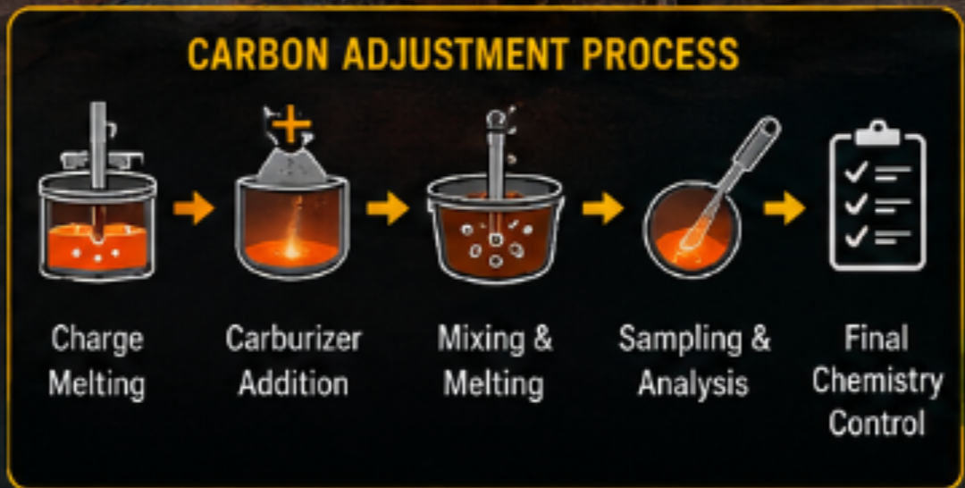
31. Complete Carbon-Control Procedure
The recommended operating sequence is:
STEP 1: SELECT THE STEEL GRADE
Establish the required chemistry and internal aim composition.
STEP 2: CHARACTERIZE RAW MATERIALS
Determine the chemistry of scrap, pig iron, DRI, returns and ferroalloys.
STEP 3: CHECK THE HEEL
Determine heel quantity and chemistry.
STEP 4: CALCULATE INITIAL CARBON
Calculate carbon contribution from all major charge materials.
STEP 5: CHARGE THE FURNACE
Follow the approved charging sequence.
STEP 6: MELT
Melt the charge under controlled operating conditions.
STEP 7: TAKE REPRESENTATIVE SAMPLE
Obtain a reliable molten-steel sample.
STEP 8: ANALYZE CHEMISTRY
Determine carbon and other grade-critical elements.
STEP 9: CALCULATE CARBON DEFICIENCY
ΔC = C_target − C_actual
STEP 10: CALCULATE CARBURIZER
M_carb = W_steel × ΔC / (100 × C_carb × R)
STEP 11: ADD CARBURIZER
Add the calculated quantity using the approved method.
STEP 12: DISSOLVE AND HOMOGENIZE
Allow sufficient time for carbon dissolution and bath mixing.
STEP 13: TAKE CONFIRMATION SAMPLE
Verify the corrected carbon level.
STEP 14: CHECK FINAL CHEMISTRY
Verify all applicable elements.
STEP 15: TAP THE HEAT
Proceed according to the approved tapping criteria.
STEP 16: RECORD ACTUAL RESULTS
Record additions, chemistry, temperature, steel weight and recovery.
STEP 17: UPDATE THE RECOVERY MODEL
Use the actual heat data to improve future calculations.
32. Carbon-Control Flowchart
RAW MATERIAL CHEMISTRY
↓
CHARGE CALCULATION
↓
HEEL CHEMISTRY
↓
ESTIMATED INITIAL CARBON
↓
FURNACE CHARGING
↓
MELTING
↓
REPRESENTATIVE SAMPLE
↓
CHEMICAL ANALYSIS
↓
ACTUAL CARBON
↓
COMPARE WITH AIM
↓
IF LOW → CALCULATE CARBURIZER
IF OK → MAINTAIN CHEMISTRY
IF HIGH → STOP CARBON ADDITION AND INVESTIGATE
↓
CONTROLLED CARBURIZER ADDITION
↓
DISSOLUTION
↓
HOMOGENIZATION
↓
CONFIRMATION SAMPLE
↓
FINAL CHEMISTRY
↓
TAPPING
↓
HEAT-WISE CARBON BALANCE
↓
CALCULATE ACTUAL RECOVERY
↓
UPDATE CHARGE-CALCULATION MODEL
33. Carbon Balance Example for a Complete Heat
Consider:
Steel scrap = 9,000 kg, C = 0.20%
Pig iron = 500 kg, C = 4.00%
Returns = 500 kg, C = 0.30%
Carburizer = 15 kg, fixed carbon = 90%
Carbon from scrap:
9,000 × 0.20 / 100 = 18 kg
Carbon from pig iron:
500 × 4.00 / 100 = 20 kg
Carbon from returns:
500 × 0.30 / 100 = 1.5 kg
Carbon from carburizer:
15 × 0.90 = 13.5 kg
Total theoretical carbon input:
18 + 20 + 1.5 + 13.5 = 53 kg
Suppose the final liquid-steel weight is 9,500 kg and final carbon is 0.45%.
Carbon retained in steel:
9,500 × 0.45 / 100 = 42.75 kg
Apparent carbon difference:
53 − 42.75 = 10.25 kg
This difference represents the apparent carbon not retained in final steel, subject to uncertainty in charge chemistry, weighing, steel weight, sampling and analysis.
34. Sources of Carbon-Balance Error
The calculated carbon balance can be affected by:
Raw-Material Variation
Scrap may not have uniform chemistry.
Weighing Error
Incorrect material weights directly affect calculated carbon.
Heel Variation
Unrecorded heel chemistry can shift the starting condition.
Carburizer Variation
Actual fixed carbon may differ from nominal values.
Sampling Error
A nonrepresentative sample produces an incorrect correction.
Analytical Error
Instrument calibration and sample preparation affect results.
Recovery Variation
Carbon recovery changes with operating conditions.
Therefore, carbon balance should always be interpreted as a process-control tool rather than an exact laboratory measurement of every carbon atom entering and leaving the furnace.
35. Methods for Improving Carbon Recovery
The following practices can improve consistency:
- Use clean and dry metallic charge materials.
- Maintain controlled carburizer particle size.
- Avoid excessive carburizer fines.
- Use consistent addition locations.
- Use accurate weighing equipment.
- Add carburizer under suitable liquid-bath conditions.
- Promote adequate bath mixing.
- Avoid unnecessary oxidizing conditions.
- Control slag condition.
- Avoid excessive holding time.
- Maintain appropriate temperature.
- Record actual carbon recovery.
- Establish separate recovery factors for different carburizer types.
- Establish recovery factors for different furnace sizes where necessary.
- Use heat-wise statistical analysis.
36. Development of a Plant-Specific Carbon-Recovery Model
A plant can develop a carbon-recovery model using historical heat data.
For example:
Heat 1: Recovery = 74%
Heat 2: Recovery = 78%
Heat 3: Recovery = 76%
Heat 4: Recovery = 81%
Heat 5: Recovery = 77%
The average recovery can be calculated and continuously updated.
However, the data should be separated when operating conditions are materially different.
For example:
- Furnace A
- Furnace B
- Petroleum coke
- Graphite
- Anthracite
- Different particle sizes
- Different addition methods.
This produces a much more useful recovery model than a single universal value.
37. Digital Carbon-Balance System
The carbon-control methodology can be implemented in a digital charge-calculation system.
Input data
- Furnace capacity
- Grade
- Charge weight
- Heel weight
- Scrap chemistry
- Pig-iron chemistry
- DRI chemistry
- Returns chemistry
- Ferroalloy chemistry
- Carburizer chemistry
- Target carbon
- Recovery factor.
Calculation
Carbon from scrap
Carbon from pig iron
Carbon from DRI
Carbon from returns
Carbon from ferroalloys
Carbon from heel
Carbon from carburizer
−
Estimated process losses
=
Predicted final carbon
Feedback
Predicted carbon
↓
Actual spectrometer carbon
↓
Difference
↓
Recovery correction
↓
Updated model
This creates a closed-loop chemistry-control system.
38. Proposed Predictive Carbon-Control Algorithm
START
↓
SELECT GRADE
↓
LOAD RAW-MATERIAL CHEMISTRY
↓
LOAD HEEL CHEMISTRY
↓
CALCULATE INITIAL CARBON
↓
ESTIMATE PROCESS LOSS
↓
PREDICT BATH CARBON
↓
MELT
↓
SAMPLE
↓
ANALYZE
↓
COMPARE ACTUAL CARBON WITH AIM
↓
CARBON LOW?
YES → CALCULATE CARBURIZER → ADD → MIX → RESAMPLE
NO ↓
CARBON WITHIN RANGE?
YES → VERIFY COMPLETE CHEMISTRY → TAP
NO ↓
CARBON HIGH?
YES → STOP CARBON ADDITION → INVESTIGATE → APPLY APPROVED CORRECTION
↓
RECORD FINAL RESULT
↓
CALCULATE ACTUAL RECOVERY
↓
UPDATE DATABASE
↓
END
39. Economic Importance of Carbon Balancing
Carbon control has a direct effect on production cost.
Poor carbon control can cause:
- Excessive carburizer consumption
- Additional alloy consumption
- Additional melting time
- Additional electrical energy
- Additional sampling
- Additional corrections
- Production delays
- Grade downgrading
- Heat rejection.
Therefore, carbon balancing is not only a chemistry-control activity. It is also a production-efficiency and cost-control activity.
40. Recommended Key Performance Indicators
A steel plant should consider monitoring:
- Average final carbon
- Carbon standard deviation
- Carbon recovery
- Carburizer consumption kg/t
- Number of carbon corrections per 100 heats
- High-carbon heat frequency
- Low-carbon heat frequency
- Heat rejection/downgrade frequency
- Average correction time
- Cost of carburizer per tonne
- Charge-calculation accuracy
- Heat-to-heat carbon variation.
41. Discussion
The analysis demonstrates that carbon control in induction-furnace steelmaking is governed by a combination of material chemistry, process conditions and measurement accuracy.
A fixed carburizer addition expressed only in kg/t may provide acceptable results when the raw-material mix and operating conditions remain extremely stable. However, such a method becomes increasingly unreliable when:
- Scrap chemistry varies
- Pig-iron percentage changes
- DRI chemistry changes
- Heel chemistry varies
- Carburizer chemistry changes
- Recovery changes
- Furnace temperature changes
- Slag oxidation changes.
The use of an actual bath analysis provides a significantly stronger basis for final carbon correction.
However, analysis alone is not sufficient. The accuracy of the correction still depends on:
- Accurate bath weight
- Carburizer composition
- Recovery factor
- Addition practice
- Dissolution
- Homogenization.
Therefore, the best system combines predictive charge calculation with analytical feedback.
42. Conclusions
Carbon adjustment and carbon balancing are fundamental aspects of induction-furnace steelmaking.
The major conclusions of this study are:
- Carbon enters the induction furnace through multiple sources.
- Steel scrap chemistry is a major contributor to carbon variation.
- Pig iron and carbon-bearing ferroalloys can significantly influence initial carbon.
- DRI chemistry and residual iron oxide should be considered.
- Liquid heel chemistry can influence the starting carbon balance.
- Carbon can be lost through oxidation, slag reactions, fume generation and incomplete assimilation.
- Carburizer fixed-carbon content alone does not determine its effectiveness.
- Particle size, temperature, slag condition, mixing and addition method influence carbon recovery.
- Carbon recovery is a process variable and should preferably be determined from plant data.
- Fixed carburizer kg/t rules are insufficient for high-accuracy chemistry control.
- Carburizer requirement should be calculated from actual carbon deficiency.
- Representative sampling is essential.
- Chemical analysis should be integrated with the charge calculation.
- Adequate dissolution and homogenization are required after carburizer addition.
- Carbon should be controlled together with other alloying elements.
- Excessive carbon should be prevented because correction can be costly.
- Heat-wise data collection allows statistical control of carbon variation.
- A plant-specific recovery database can significantly improve charge calculations.
- Digital charge-calculation systems can use analytical feedback to continuously improve carbon prediction.
- The ultimate objective is stable final chemistry with minimum unnecessary carbon consumption.
The fundamental principle can therefore be summarized as:
ACCURATE CARBON CONTROL
=
ACCURATE CHARGE BALANCE
RELIABLE CHEMICAL ANALYSIS
REALISTIC CARBON RECOVERY
CONTROLLED CARBURIZER ADDITION
ADEQUATE HOMOGENIZATION
FINAL VERIFICATION
Carbon control should therefore be regarded not as a single furnace operation, but as a complete process-control system extending from raw-material selection to final steel chemistry.
43. Practical Engineering Checklist
Before each heat, verify:
[ ] Steel grade confirmed
[ ] Raw-material chemistry available
[ ] Scrap segregated correctly
[ ] Charge weights verified
[ ] Heel quantity known
[ ] Heel chemistry considered
[ ] Carburizer chemistry verified
[ ] Initial carbon calculated
[ ] Furnace fully melted/defined sampling condition reached
[ ] Representative sample taken
[ ] Spectrometer result verified
[ ] Carbon deficiency calculated
[ ] Recovery factor selected
[ ] Carburizer quantity calculated
[ ] Addition weighed
[ ] Addition performed safely
[ ] Adequate dissolution time provided
[ ] Bath homogenized
[ ] Confirmation sample taken
[ ] Final chemistry verified
[ ] Final steel weight recorded
[ ] Actual carbon recovery calculated
[ ] Heat data entered into database
44. Final Engineering Statement
The most important principle of carbon control in induction-furnace steelmaking is:
“Do not treat carburizer addition as a fixed recipe. Treat carbon as a controlled material balance.”
The furnace operator should know:
- How much carbon entered with the metallic charge.
- How much carbon was present in the heel.
- How much carbon entered through ferroalloys.
- How much carbon was intentionally added.
- How much carbon is present in the bath.
- How much carbon is expected to be lost.
- What carbon recovery is being achieved.
- How much additional carbon is actually required.
- Whether the added carbon has completely dissolved.
- Whether the final chemistry has been verified.
The ultimate objective is not maximum carbon addition or maximum carbon recovery.


Comments 0
Be the first to share your thoughts.
Leave a comment
Your comment will appear after a quick moderation check.