
Introduction
The refractory lining is one of the most critical components of an induction furnace. It separates the molten metal from the furnace coil and supporting structure while withstanding high temperatures, thermal cycling, mechanical wear and chemical interaction with slag and metal.
A properly installed lining helps maintain safe furnace operation, consistent melting performance and predictable campaign life. Poor material selection, inadequate compaction, incorrect sintering or delayed detection of lining wear can lead to premature failure, unplanned shutdowns and potentially catastrophic molten-metal leakage.
For this reason, induction furnace lining should not be treated as a simple refractory-filling activity. It is a controlled engineering process involving material selection, furnace preparation, installation, compaction, sintering, acceptance inspection and ongoing condition monitoring.
This guide explains the typical process for a coreless induction furnace using a dry ramming-mass working lining, with practical considerations for steel plant engineers, refractory technicians, furnace operators and maintenance teams.
Important: The exact installation method, lining dimensions, ramming requirements and sintering cycle must follow the furnace manufacturer's instructions and the technical data for the selected refractory. The procedure for one refractory grade or furnace cannot automatically be applied to another.
1. What Is an Induction Furnace Lining?
An induction furnace lining is a refractory layer installed inside the furnace shell and induction-coil assembly. Its primary purpose is to contain the molten metal and protect the equipment beneath it.
<AsyncImage query="coreless induction melting furnace cutaway diagram refractory working lining copper induction coil steel shell" aspectRatio="16:9" width="100%"/>
Main functions of the lining
Containment: Holds the molten metal within the designed furnace cavity.
Electrical and equipment protection: Separates the molten bath from the induction coil and associated components.
Thermal resistance: Withstands the operating temperature and heat flux.
Chemical resistance: Resists attack from the molten metal, slag and process contaminants.
Mechanical resistance: Withstands charging impact, bath movement and normal operating stresses.
Thermal-shock resistance: Accommodates temperature changes within the limits of the refractory system.
Dimensional stability: Maintains the required crucible geometry during the campaign.
The lining must be designed and installed to provide the required thickness and geometry while remaining compatible with the furnace's electrical and thermal design.
2. Understand the Different Components of the Lining System
The term furnace lining is sometimes used for several different materials. Understanding their functions prevents installation mistakes.
| Component | Primary function |
|---|---|
| Working lining | Directly contacts the molten metal and slag |
| Dry ramming mass | Refractory granular material compacted to form the working lining |
| Coil coating or protective layer | Protects the coil assembly as specified by the furnace design |
| Backup insulation | Reduces heat transfer to surrounding structures where included in the design |
| Furnace former | Defines the internal shape and dimensions of the new lining during installation |
| Spout and lip refractory | Protects the tapping or pouring area against local erosion and thermal stress |
| Repair or patching material | Restores selected worn areas where an approved repair procedure permits |
These components are not interchangeable. For example, ceramic fibre may be used as insulation in a designed location, but it is not a substitute for the main load-bearing working lining.
Likewise, refractory bricks, castables and dry ramming masses are different lining systems. The correct choice depends on furnace construction, metal grade, operating conditions and the equipment supplier's design.
3. Step 1 — Select the Correct Refractory Material
Refractory selection is the first major decision in lining preparation. The material must be suitable for the metal being melted, the slag chemistry, the operating temperature and the expected thermal cycle.
3.1 Common refractory systems
Silica-based acidic ramming mass
Silica ramming mass is widely used in induction melting applications where its chemistry is compatible with the metal and slag practice. It forms a silica-rich working lining and is often selected for conventional carbon-steel or iron-melting operations, subject to the specific operating conditions.
Magnesia-based basic ramming mass
Magnesia-based refractories may be selected for applications requiring basic refractory chemistry. Compatibility with the steel grade, slag, refractory installation method and furnace design must be confirmed.
Neutral refractory systems
Alumina-based and alumina-spinel systems are used in certain steel and alloy-melting applications where neutral refractory chemistry and specific resistance to slag attack are desired.
No refractory family is automatically best for every induction furnace. The appropriate material must be selected against the actual operating conditions.
3.2 Factors affecting refractory selection
Before purchasing the lining material, review:
Type of metal and steel grades being melted.
Scrap, DRI, pig iron and other charge proportions.
Expected slag chemistry and quantity.
Operating temperature and superheat requirements.
Frequency of furnace starts, stops and thermal cycling.
Required campaign life and permitted maintenance practices.
Furnace size, coil geometry and lining thickness.
Supplier's recommended installation and sintering procedure.
The refractory supplier should provide the relevant technical data sheet, storage requirements, installation instructions, sintering schedule and recommendations for inspection or repair.
4. Step 2 — Prepare the Furnace for Relining
Proper preparation is essential before installing new refractory.
4.1 Isolate the equipment
Before work begins:
Stop the furnace and allow it to reach a safe condition under the approved shutdown procedure.
Isolate electrical, hydraulic and other relevant energy sources.
Apply the plant's lockout/tagout and verification procedure.
Confirm that molten metal and residual hot material have been removed or managed safely.
Establish a controlled work area and confirm that the lining team is authorised for the task.
The actual isolation procedure must follow the equipment design and the plant's safety management system.
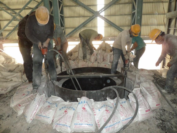
4.2 Remove the old lining
Remove the spent working lining using the approved method and suitable tools.
During removal:
Protect the induction coil and supporting structures.
Avoid uncontrolled impact or damage to the coil coating.
Follow the manufacturer's instructions for any required coil or insulation inspection.
Remove loose refractory and debris from the installation area.
Inspect for signs of overheating, metal penetration, mechanical damage or abnormal wear.
If there is evidence of molten-metal penetration, coil damage or suspected breakout, stop and obtain a qualified inspection before proceeding.
4.3 Clean and inspect the furnace
The furnace must be clean and suitable for the new lining system.
Inspect:
Coil condition and visible coil coating.
Furnace shell and supporting structures.
Bottom support and crucible geometry.
Earth-leakage or lining-breakout detection components, where fitted.
Cooling-water circuits and associated monitoring systems.
Any designated backup insulation or protective layer.
Any defective components must be repaired or replaced according to the equipment manufacturer's instructions.
4.4 Ensure suitable dryness
Moisture in the furnace assembly or refractory system can be hazardous when exposed to molten metal and high temperatures.
Confirm that the furnace and any relevant components meet the dryness requirements specified for the lining system. Do not assume that visual appearance alone proves that an assembly is dry.
Safety warning: Contact between water and molten metal can cause violent steam expansion and metal ejection. Do not proceed if moisture, water leakage or an uncertain equipment condition remains unresolved.
5. Step 3 — Check the Ramming Mass Before Installation
Before installation, verify that the delivered material is correct and suitable for use.
Material checks
Product name and refractory grade.
Batch or lot number.
Manufacturing and expiry or shelf-life information, where applicable.
Packaging integrity and evidence of moisture ingress.
Storage conditions and material condition.
Particle-size specification and technical data sheet.
Compatibility with the planned furnace lining system.
Keep the material in the manufacturer's recommended storage conditions. Material that is damp, contaminated, caked or otherwise outside its specified condition should be quarantined until its suitability is confirmed.
Why particle-size distribution matters
Ramming mass is formulated with a controlled distribution of refractory grains and fines. This distribution affects packing, compaction and the development of the lining structure during sintering.
Do not independently sieve, blend, add a binder to or otherwise modify a commercial ramming mass unless the supplier's approved procedure specifically requires it. Such changes can alter the installation and sintering behaviour.
6. Step 4 — Install the Former and Prepare the Working Geometry
A furnace former is used to establish the internal shape of the new crucible lining.
The former must match the specified dimensions and be suitable for the furnace design. Incorrect centring or dimensions can create uneven wall thickness, an incorrect bath volume or local regions of reduced protection.
Before ramming:
Verify the former dimensions against the approved lining drawing.
Position and secure the former as specified.
Check centring and alignment.
Confirm the required bottom and sidewall geometry.
Verify that the required protective and detection components are correctly installed.
The former's material, surface preparation, release method and removal procedure are system-specific. Follow the approved installation instructions rather than using a generic method.
7. Step 5 — Install and Compact the Bottom Lining
The bottom lining provides the base of the working crucible and must support the metal bath under operating conditions.
For a dry ramming-mass system, the material is generally placed in controlled layers and compacted using suitable tools.
Typical installation principles
Place the specified quantity of material uniformly.
Follow the supplier's specified layer thickness.
Compact each layer using the approved rammer or compaction method.
Maintain uniform coverage and avoid unrammed pockets.
Prepare the surface between layers as required by the installation procedure.
Maintain the specified bottom thickness and geometry.
Some dry ramming systems use a flat-headed rammer for broad areas and a pointed or spiked rammer for selected locations. Tool selection and use must follow the material supplier's method.
Why uniform compaction matters
Insufficient or uneven compaction can leave regions with different density and mechanical behaviour. These regions may sinter inconsistently and can contribute to cracking, penetration or premature wear during service.
Overly aggressive or inappropriate compaction can also damage components or create installation defects. The goal is uniform compaction using the specified procedure, not simply maximum force.
8. Step 6 — Install the Sidewall Lining
After the bottom has been completed to the specified geometry, the sidewall working lining is installed around the former.
Key controls
Uniform layer placement: Distribute the material evenly around the circumference.
Controlled compaction: Compact each layer according to the supplier's prescribed method.
Consistent wall thickness: Maintain the designed clearance between the former and the surrounding furnace structure.
Avoiding layer defects: Prepare the surface between successive layers as specified.
Former alignment: Recheck centring during installation so that the crucible does not become eccentric.
Protection of components: Prevent ramming tools from damaging the coil coating, detection components or other protected assemblies.
Common sidewall installation defects
Uneven wall thickness.
Loose or poorly compacted sections.
Material segregation.
Contamination by foreign material.
Gaps at the bottom-to-wall transition.
Damage to the former or surrounding components.
Deviations from the approved crucible profile.
The installation team should record the checks required by the plant's quality plan before the next stage begins.
9. Step 7 — Complete the Top Ring, Lip and Tapping Area
The top ring and tapping or pouring area may experience different mechanical and thermal stresses from the main sidewall.
The top geometry must be formed according to the approved design, using the specified refractory and installation procedure.
Pay particular attention to:
Correct top-ring geometry.
Uniform material placement and compaction.
Protection of the coil and surrounding structure.
The designed shape of the furnace lip or pouring spout.
Compatibility of repair or spout materials with the working lining.
The transition between the main lining and local refractory components.
Poorly formed or badly maintained lip and spout regions can contribute to local erosion and operational difficulties even when the main crucible remains in acceptable condition.
10. Step 8 — Inspect the Installed Green Lining
After installation and before sintering, inspect the lining according to the supplier's and furnace manufacturer's acceptance criteria.
A newly rammed lining is sometimes described as a green lining. It has not yet completed the thermal process needed to develop the required working structure.
Installation acceptance checklist
Correct refractory material and batch documented.
Required lining dimensions and profile verified.
Bottom and sidewall geometry checked.
Uniformity and compaction records reviewed.
No visible installation defects outside acceptance limits.
Former and temporary components managed according to the procedure.
Protective and detection systems checked.
Required records and approvals completed.
Do not rely only on visual appearance. The acceptance process should use the measurements and checks specified by the lining supplier and plant procedure.
11. Step 9 — Sinter the Lining Correctly
Sintering is one of the most critical stages of the lining process.
The newly installed refractory must be heated according to a controlled schedule so that the material develops the structure and bonding characteristics required for service. The details depend on refractory chemistry, grain structure, binder system, installation condition and furnace design.
<AsyncImage query="industrial induction furnace refractory lining sintering first heat glowing furnace interior steel foundry" aspectRatio="16:9" width="100%"/>
Why sintering is necessary
A correctly installed but improperly sintered lining may not withstand service conditions as intended.
An unsuitable heating cycle can contribute to:
Uneven sintering.
Inadequate bonding in parts of the lining.
Excessive thermal stress.
Cracking or spalling.
Premature metal penetration or erosion.
Reduced lining campaign life.
Key sintering controls
Follow the approved heating curve. Use the specific schedule supplied for the refractory and furnace combination.
Control the heating rate. Follow the prescribed stages and limits rather than applying power according to guesswork.
Monitor the process. Record the relevant electrical, temperature and time data available under the approved procedure.
Use the specified initial charge and melt-in method. Charge material, loading sequence, operating conditions and initial heats must follow the refractory supplier's instructions.
Observe the prescribed hold periods. Do not shorten stages simply to save time or energy.
Document deviations. Unexpected interruptions or departures from the schedule should be assessed by the responsible technical personnel before the furnace is released for normal operation.
Is there one standard sintering schedule for every induction furnace?
No. A single time-temperature schedule cannot safely be applied to every furnace lining.
The schedule may differ between silica, magnesia and neutral ramming masses, and between products using different bonding systems. Furnace capacity alone does not determine the correct heating curve.
Do not use a generic schedule from an unrelated furnace or refractory product. The manufacturer's instructions for the exact refractory grade and installation are the controlling reference.
12. Step 10 — Inspect and Release the Furnace for Operation
After the approved sintering and initial operating procedure have been completed, the responsible team should confirm that the furnace meets the plant's acceptance requirements.
Pre-production checks
Review the installation and sintering records.
Inspect accessible areas for abnormalities.
Verify the condition of the furnace lip and other critical refractory zones.
Confirm that cooling-water systems and monitoring instruments are functioning correctly.
Verify the status of lining-breakout or earth-leakage detection systems where fitted.
Confirm that all safety interlocks and protective devices are available.
Record the lining installation date, refractory batch and campaign identification.
Obtain the required authorisation before normal production begins.
A lining that has completed sintering is not automatically safe if other equipment defects remain. Furnace readiness must include the supporting electrical, cooling, hydraulic and safety systems.
13. Important Parameters Affecting Lining Life
Lining life is influenced by the combined effects of material selection, installation quality and operating practice.
| Parameter | Why it matters | Control approach |
|---|---|---|
| Refractory chemistry | Determines compatibility with metal and slag | Select material for the actual application |
| Particle-size distribution | Influences packing and compaction | Use the specified commercial grade |
| Material condition | Moisture or contamination can affect installation | Inspect storage and packaging |
| Lining thickness | Affects containment, thermal performance and usable capacity | Follow approved furnace drawings |
| Former alignment | Influences wall uniformity | Verify centring during installation |
| Compaction uniformity | Affects the consistency of the installed lining | Use the specified layer and ramming method |
| Sintering cycle | Develops the required working structure | Follow the product-specific heating schedule |
| Slag chemistry | Can accelerate chemical attack | Maintain a compatible, validated slag practice |
| Charging impact | Can damage the lining mechanically | Use controlled charging procedures |
| Thermal cycling | Can create thermal stress | Follow the approved operating and shutdown practices |
| Lining wear | Reduces the remaining protective thickness | Inspect and monitor against defined limits |
| Cooling-water condition | Abnormalities can indicate serious equipment risks | Monitor continuously and respond to alarms |
14. How to Monitor Lining Wear During Operation
Lining wear is a progressive condition that must be managed throughout the furnace campaign.
A robust lining-management programme combines operating records, scheduled inspection, approved measurement techniques and monitoring systems.
14.1 Track campaign performance
Maintain records of:
Installation and commissioning date.
Refractory grade and batch number.
Number of heats and operating hours.
Metal grades and charge mix.
Abnormal operating events.
Slag-related changes and observed wear.
Repairs and patching history.
Inspection results and lining retirement decisions.
These records help identify whether a change in campaign performance is associated with material variation, installation practice, operating conditions or another factor.
14.2 Use approved inspection and detection methods
Depending on the furnace, the plant may use visual inspections, specified wear measurements, lining-breakout detection systems or other monitoring technologies.
Electrical lining-monitoring systems can provide important warnings, but they do not replace physical inspection, preventive maintenance or the manufacturer's lining-retirement criteria.
Never continue operating merely because a detection system has not alarmed if physical evidence suggests dangerous lining wear or possible metal penetration.
14.3 Establish retirement criteria
The plant should define clear criteria for:
Continued operation.
Inspection or technical assessment.
Approved local repair, if permitted.
Complete relining.
Emergency shutdown where unsafe conditions are suspected.
The minimum acceptable lining thickness and any repair limits must be established for the particular furnace and refractory system.
15. Common Lining Problems and Their Possible Causes
| Problem | Possible contributing factors | Recommended response |
|---|---|---|
| Premature lining erosion | Incompatible refractory or slag, high wear, unsuitable operating practice | Review refractory selection, slag history and wear measurements |
| Cracking or spalling | Thermal stress, unsuitable heating cycle, installation defects or operating excursions | Inspect and investigate before further use |
| Uneven lining thickness | Incorrect former positioning or inconsistent installation | Verify geometry during installation and correct before sintering |
| Localised wear near the lip | Tapping-area erosion, slag interaction or mechanical stress | Inspect the lip and use approved refractory repair practices |
| Reduced campaign life | Material variability, poor compaction, sintering deviations or changed operating conditions | Compare records across campaigns |
| Abnormal metal penetration | Lining damage, inadequate thickness or chemical incompatibility | Apply the approved safety response and assess the furnace condition |
| Cooling-water alarm or suspected leakage | Equipment fault or abnormal cooling-circuit condition | Follow the emergency procedure immediately |
These are possible causes, not definitive diagnoses. A root-cause investigation should consider the actual refractory, furnace geometry, process history and inspection evidence.
16. Safety Precautions During Lining Work
Induction furnace relining involves hot surfaces, heavy equipment, refractory dust, electrical hazards and potentially fatal molten-metal risks.
The plant must conduct the work under its approved risk assessment, permit-to-work system and equipment-specific procedure.
Essential controls
Isolate and verify all relevant energy sources before maintenance.
Ensure that the furnace is in the required safe state.
Use appropriate respiratory protection and other PPE for refractory dust and handling hazards.
Follow the material safety data sheet and refractory handling instructions.
Prevent moisture ingress into the furnace and charge materials.
Keep the work area controlled and free from unnecessary personnel.
Use approved lifting and handling equipment.
Protect the induction coil, cooling circuits and monitoring components.
Verify protective systems and interlocks before commissioning.
Keep records of installation, sintering and release approvals.
If lining failure is suspected
If the furnace shows signs of breakout, abnormal metal leakage, suspected metal penetration, critical cooling-water abnormalities or another dangerous condition, follow the plant's emergency procedure immediately.
Do not approach the furnace to attempt an improvised repair. Do not bypass protection systems or resume melting without the required technical inspection and formal clearance.
For Indian steel plants, consult the Ministry of Steel's Process Based Safety Guidelines for the Iron & Steel Sector, including the induction-furnace guidance.
Reference: https://steel.gov.in/safety-guidelines-iron-steel-sector
17. Best Practices for Extending Lining Campaign Life
Long lining life is achieved through a combination of good materials, correct installation, controlled sintering and disciplined operation.
Standardise refractory procurement. Use approved grades and maintain batch traceability.
Train the installation team. Ensure that technicians understand the required compaction and inspection method.
Use approved installation drawings. Verify former dimensions and lining thickness before ramming.
Document compaction and sintering. Keep records that can be compared between campaigns.
Avoid unauthorised changes. Do not modify refractory mixtures or heating schedules without technical approval.
Control slag practice. Use a practice compatible with the selected refractory.
Prevent mechanical damage. Follow approved charging and tapping methods.
Monitor wear. Combine operating records with inspection and suitable detection systems.
Review abnormal events. Investigate every suspected penetration, abnormal wear pattern or unexplained reduction in lining life.
Use campaign data for improvement. Compare refractory consumption, campaign duration, repair frequency and safety observations.
Conclusion
Induction furnace lining is a critical engineering activity that directly affects furnace containment, operating reliability, refractory consumption and safety.
The main stages are furnace preparation, refractory selection, former installation, bottom and sidewall ramming, completion of the top and lip areas, installation inspection, controlled sintering and release for operation. The work does not end when the new lining is installed: ongoing wear monitoring, maintenance and clear retirement criteria are equally important.
The most important principle is to follow the installation and sintering requirements for the exact refractory and furnace system, rather than relying on a generic procedure.
A well-managed lining programme helps reduce avoidable failures, improve campaign consistency and protect people and equipment. Every lining should be installed, inspected and released under the responsibility of trained personnel using the approved technical documentation.
Frequently Asked Questions
1. What is the purpose of induction furnace lining?
It contains the molten metal, protects the induction coil and supporting structure, and resists thermal, chemical and mechanical stresses during melting.
2. Which ramming mass is best for an induction furnace?
There is no universal best material. Silica, magnesia and neutral refractory systems each have suitable applications. The choice depends on metal grade, slag chemistry, operating practice and furnace design.
3. What is dry ramming mass?
Dry ramming mass is a granular refractory material installed and compacted in a controlled manner to form the working lining of a suitable furnace. Its exact installation requirements depend on the product formulation.
4. Why is compaction important during lining installation?
Uniform compaction helps create a consistent lining structure. Poor or uneven compaction can contribute to defects and inconsistent sintering, potentially reducing service life.
5. What is sintering in an induction furnace lining?
Sintering is the controlled thermal process that develops the required structure and bonding characteristics of the installed refractory lining. It must follow the specific product and furnace instructions.
6. Can the same sintering schedule be used for all ramming masses?
No. Different refractory compositions, binders and furnace designs can require different heating curves. Use the approved schedule for the exact product and installation.
7. How can lining wear be monitored?
Use the furnace manufacturer's inspection method, campaign records, approved wear measurements and installed monitoring systems where available. Detection systems do not replace physical inspection or lining-retirement criteria.
8. What causes premature lining failure?
Potential causes include unsuitable refractory selection, installation defects, poor compaction, incorrect sintering, chemical attack, mechanical damage and operation beyond approved wear limits.
9. Can a worn lining be repaired instead of replaced?
Some lining systems permit approved local repairs or patching within defined limits. Whether repair is acceptable depends on the location and extent of damage, the remaining lining condition and the manufacturer's instructions.
10. What is the most important safety precaution during relining?
Use the plant's approved isolation, permit-to-work and emergency procedures, prevent moisture exposure, protect critical equipment and do not operate a furnace with suspected lining failure.
References and Further Reading
Ministry of Steel, Government of India — Safety Guidelines for the Iron & Steel Sector, including process-based guidance for induction furnaces.
https://steel.gov.in/safety-guidelines-iron-steel-sectorIndian Foundry Journal / Foundry Talks — Application / Installation of Dry Ramming Mass in Induction Furnace.
https://indianfoundry.org/upload/pdf/FOUNDRY%20TALKS-%20WR%20AUGUST%202023.pdfSaint-Gobain Performance Ceramics & Refractories — Working Linings for Coreless Induction Furnaces.
https://www.ceramicsrefractories.saint-gobain.com/refractory-solutions/iron-and-steelmaking/working-liningsDFP India — Neutral Ramming Mass and Refractory Information.
https://dfpindia.com/furnace-lining-material
Technical disclaimer: This article is intended for professional education and general engineering reference. It is not a substitute for the furnace manufacturer's manual, refractory supplier's product-specific instructions, the plant's approved SOP, statutory requirements or a qualified refractory engineer's assessment.
Comments 0
Be the first to share your thoughts.
Leave a comment
Your comment will appear after a quick moderation check.