Steel Making in an Induction Furnace: Step-by-Step Operating Practice, Process Parameters and Quality Control
Introduction
Steel making in an induction furnace is an important production route in India's secondary steel industry. It is widely used to manufacture liquid steel for casting into ingots and billets, which may subsequently be processed into TMT bars, structural sections and other steel products.

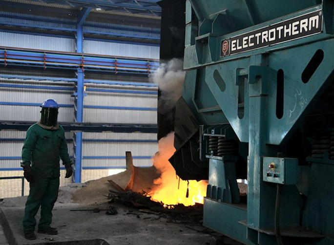
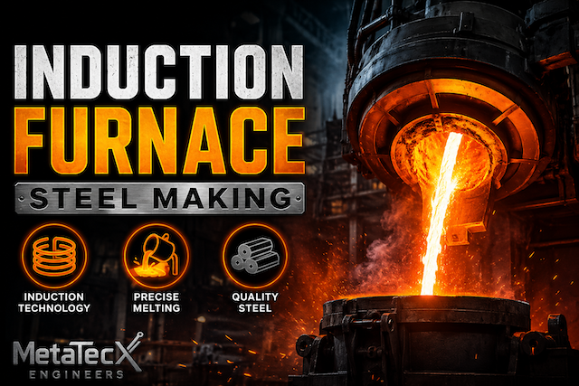
Figure 1. Coreless induction furnace during steel melting.
Successful production requires more than simply melting scrap or sponge iron. The operator must control the raw-material mix, energy consumption, melting sequence, slag condition, temperature, chemical composition, tapping practice and casting conditions.
An induction furnace can provide rapid melting and electromagnetic stirring, which help distribute heat and alloying additions. However, melting and refining are not the same operation. Conventional induction furnaces generally have limited refining capability compared with dedicated steelmaking and secondary-metallurgy units. The quality of the final steel therefore depends heavily on charge quality, process discipline and any additional refining facilities available at the plant. [1][2]
This guide explains the typical operating sequence, important process parameters, quality checks and safety practices involved in induction furnace steelmaking.
1. What Is an Induction Furnace?
An induction furnace is an electrically powered melting unit that uses electromagnetic induction to heat metal.
An alternating current passes through a water-cooled copper coil surrounding a refractory-lined crucible. The resulting alternating magnetic field induces electrical currents in the conductive metallic charge. Electrical resistance generates heat, melting the charge.
Electromagnetic forces also circulate the molten metal, helping distribute temperature and mix the bath.
Main components
- Induction coil: Produces the alternating magnetic field.
- Refractory lining: Contains the molten metal and protects the coil assembly.
- Power supply and transformer: Supply electrical energy at the required operating conditions.
- Capacitor bank or power-factor compensation system: Supports the electrical system as designed.
- Cooling-water circuit: Removes heat from the coil, power cables and other water-cooled components.
- Hydraulic tilting mechanism: Enables controlled furnace tilting for tapping.
- Temperature measurement and sampling equipment: Support process control and quality verification.
- Protective and monitoring systems: May include cooling-water monitoring, earth-leakage or lining-breakout detection, interlocks and alarms, depending on the installation.
The plant's approved operating manual and equipment design determine the actual operating limits and control procedures.
2. Raw Materials and Charge Preparation
The first major production decision is the selection of raw materials. Poor charge quality can increase power consumption, reduce metallic yield, complicate slag handling and cause the final steel to miss its chemistry targets.

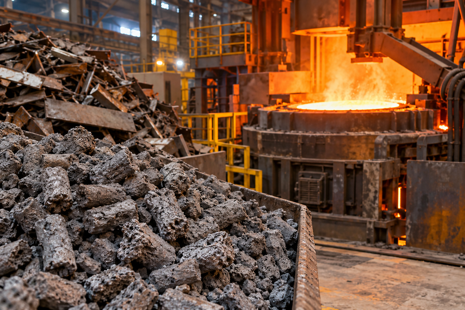
Figure 2. Typical charge materials used in induction furnace steelmaking.
2.1 Common charge materials
Steel scrap: Can provide metallic iron with relatively low melting losses when its grade, cleanliness and chemistry are suitable.
Direct reduced iron (DRI or sponge iron): Provides metallic iron with varying amounts of residual oxides, gangue and carbon. Its metallization, total iron, FeO, carbon, phosphorus and sulfur levels can influence energy demand, slag generation and final chemistry.
Pig iron or other iron-bearing materials: May be used where permitted by the required grade and plant practice. Their carbon, silicon, phosphorus and sulfur contents must be considered.
Ferroalloys: Materials such as ferromanganese, ferrosilicon and ferrochrome are selected according to the target steel grade.
Fluxes and slag-forming materials: These may include lime, dolomite or other approved materials. Their use depends on the lining, slag practice and process objective; adding flux alone does not guarantee effective impurity removal.
2.2 Charge preparation checklist
Before charging, the responsible team should:
- Verify the source, grade and chemistry of the raw materials.
- Inspect scrap for excessive rust, dirt, paint, oil, sealed containers and other contaminants.
- Keep charge materials dry and free from hazardous moisture.
- Determine the batch proportions from the required steel grade and material analysis.
- Estimate expected metallic yield, slag generation and alloy requirements.
- Confirm that charge dimensions and weight are compatible with the furnace and charging equipment.
- Record the heat number and raw-material traceability details.
Moisture contamination is particularly dangerous because contact between water and molten steel can cause violent steam expansion and metal ejection.
3. Furnace and Equipment Readiness
Before the heat begins, the operator should confirm that the furnace and its supporting systems are fit for operation.

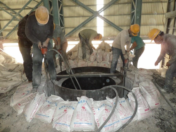
Figure 3. Example of a furnace cooling-water system; use equipment-specific inspection criteria.
Inspect the following:
- Refractory lining condition and lining-life records.
- Furnace lip, working platform and tilting mechanism.
- Cooling-water flow, pressure, temperature and alarms.
- Power supply, electrical connections, protective interlocks and earthing arrangements.
- Exhaust and fume-collection systems.
- Temperature measurement and sampling equipment.
- Ladle condition, refractory integrity and preheating status.
- Emergency equipment, communication arrangements and access routes.
Any suspected lining failure, abnormal cooling-water condition, damaged electrical component or failed safety interlock must be addressed under the plant's approved procedure before operation.
Important: A coreless induction furnace with a rammed refractory lining and a small induction furnace using a prefabricated crucible may require different lining preparation and heating procedures. Use the procedure approved for the specific furnace and refractory system.
4. Charging the Furnace
Charging is normally carried out according to the approved sequence for the furnace and raw-material mix.
A typical approach is to introduce suitable metallic charge, melt it, and add further charge in controlled batches as furnace capacity and the operating procedure permit. The exact sequence depends on the furnace design, charge density, DRI proportion, scrap dimensions and plant practice.
Key operating considerations
- Avoid excessive impact against the refractory lining.
- Prevent bridging, hanging charge and unsafe overfilling.
- Maintain the correct furnace loading limits.
- Follow the approved power-on and charging sequence.
- Introduce DRI and other fine or low-density materials only by the specified method.
- Keep personnel clear of charging hazards and potential splash zones.
The furnace is not normally brought to the melting temperature before the entire cold metallic charge is introduced. Rather, the charge is loaded and heated according to the approved melting sequence.
5. Melting the Charge
Once the charge is in the furnace and operating conditions have been verified, electrical power is applied according to the furnace operating procedure.

Figure 4. Illustrative view of the melting stage.
As the metallic material heats and melts, the operator monitors the electrical load, melt progression, charge movement and furnace condition.
5.1 Typical melting stages
Stage 1 — Initial heating: The charge warms and begins to melt. Stable operation and correct loading are important.
Stage 2 — Progressive melting: Additional charge may be introduced in controlled batches. Operators monitor power input, melting rate and the risk of bridging.
Stage 3 — Formation of a liquid bath: As the charge melts, electromagnetic stirring helps circulate the liquid metal and distribute heat.
Stage 4 — Completion of melting: The operator verifies that unmelted pieces are no longer present where they would compromise safe tapping or the next process stage.
5.2 Factors affecting melting performance
- Furnace power and operating frequency.
- Charge size, density and packing.
- Scrap-to-DRI ratio.
- DRI metallization and residual oxide content.
- Charge moisture and contamination.
- Slag quantity and composition.
- Power interruptions and charging delays.
- Refractory condition and furnace operating practice.
The objective is not simply to achieve the fastest melting rate. A good operation balances productivity, electrical energy consumption, metallic yield, refractory life and steel quality.
6. Slag Formation and Process Control
Slag is the non-metallic phase that forms from oxides, gangue, fluxes, refractory interaction and other constituents. Its composition and condition can affect metal cleanliness, heat transfer, yield and refractory wear.
In induction furnaces, slag practice must be compatible with the refractory lining and the intended metallurgical objective.
Why slag management matters
- Excessive slag can increase iron losses and complicate tapping.
- Unfavourable slag chemistry can accelerate refractory wear.
- Poorly controlled slag can carry unwanted inclusions into the steel.
- DRI-derived gangue and residual oxides can increase slag volume and energy demand.
- Incorrect flux selection can create operating difficulties rather than improve refining.
Can an induction furnace remove phosphorus and sulfur?
This is an important question for steelmakers.
Conventional induction furnaces are generally used primarily for melting and composition adjustment. Their ability to remove phosphorus and sulfur is limited by factors such as slag chemistry, refractory compatibility, slag-metal contact and operating conditions. Conventional acidic silica-based linings can restrict the use of strongly basic refining slags.
Specially developed fluxes and controlled refining practices have been investigated for induction furnaces, including work by CSIR–National Metallurgical Laboratory. Such results depend on the specific process, lining and operating conditions and should not be treated as universal performance guarantees.
Therefore:
- Select low-phosphorus and low-sulfur charge materials when the grade requires tight limits.
- Analyse the charge and finished steel.
- Use only an established, validated refining practice where the plant is equipped for it.
- Provide ladle refining or another suitable secondary-metallurgy route when required by the grade and quality specification.
Do not assume that adding limestone or another flux will automatically correct high phosphorus or sulfur.
7. Temperature Measurement and Control
Temperature control is critical because the steel must be hot enough for the next operation without being unnecessarily overheated.
An insufficient tapping temperature may cause poor ladle filling, premature solidification or casting difficulties. Excessive superheat can increase energy consumption and may contribute to refractory wear, oxidation and unwanted changes in the melt.
7.1 Recommended control approach
- Use a calibrated temperature-measurement system appropriate for molten steel.
- Measure at the stage specified by the plant's process-control procedure.
- Consider expected heat losses during tapping, transfer and casting.
- Confirm the target temperature for the steel grade and downstream equipment.
- Avoid unnecessary holding or overheating.
- Record the temperature against the heat number.
The target temperature must be determined from the steel grade, ladle condition, transfer time, casting system and plant operating data. There is no single temperature suitable for every induction furnace heat.
For many conventional carbon-steel operations, liquid-steel temperatures are in the vicinity of 1,600–1,650°C, but this is only a broad reference range—not a universal tapping instruction. The approved process specification must govern actual operation.
8. Chemical Analysis and Steel Composition Adjustment
A molten bath may appear uniform while still failing the required chemistry. Visual inspection cannot replace chemical analysis.
8.1 Sampling and testing
At the sampling stage defined by the plant procedure:
- Collect a representative sample using the approved equipment.
- Identify the sample with the heat number.
- Analyse the elements required by the product specification.
- Compare the results with the target range and applicable standard.
- Calculate any permitted composition corrections.
- Re-sample or re-test when required by the quality plan.
Depending on the grade, important elements may include carbon, manganese, silicon, phosphorus, sulfur, chromium, nickel and other alloying elements.
8.2 Alloy addition
Alloy additions should be calculated from the bath mass, current analysis, target chemistry, material composition and expected recovery.
A simplified mass-balance relationship for an alloying element is:
Alloy Addition Calculation
Estimated Alloy addition (kg) ≈ Required element increase (kg) / (Element fraction in alloy × Recovery fraction)
The calculation is an estimate and must account for actual process conditions, dissolution, oxidation, and sampling uncertainty.
Worked Example
If a 5,000 kg heat needs an increase of 0.10 percentage points in an element, the theoretical element increase is calculated as follows:
5,000 × (0.10 / 100) = 5 kg
If the alloy contains 75% of that element and the assumed recovery is 90%, the estimated alloy addition is:
5 / (0.75 × 0.90) ≈ 7.41 kg
Important Note
Use the result as a starting estimate only. Confirm the actual alloy composition, heat mass, target chemistry, recovery assumptions, and laboratory/sample results before finalizing additions.
This is an illustrative calculation only. Actual additions must be approved by the responsible metallurgist using the plant's validated recovery factors and the required chemistry limits.
8.3 Important control principles
- Avoid relying on nominal alloy composition without checking the certificate or actual material specification.
- Account for the existing element content in the bath.
- Consider recovery differences between elements and process conditions.
- Avoid uncontrolled late additions that may not dissolve or homogenize sufficiently.
- Confirm the final analysis against the product specification before release.
9. Final Temperature, Tapping and Ladle Practice
Once the steel chemistry and temperature meet the required process criteria, the heat can be prepared for tapping.

Figure 6. Illustrative molten-steel tapping operation into a prepared ladle.
The operator should verify that the receiving ladle is suitable, correctly positioned and prepared according to the plant's ladle-management procedure.
Tapping checklist
- Confirm the heat identity and release status.
- Verify the target tapping temperature.
- Confirm ladle condition and readiness.
- Check that personnel are outside the designated danger zone.
- Ensure the tapping area and transfer route are clear.
- Operate the tilting system using the approved controls.
- Minimise avoidable delays and uncontrolled splashing.
- Follow the approved slag-carryover control practice.
- Record tapped weight, temperature and relevant observations.
Where secondary refining is available, the steel may proceed to the appropriate ladle-treatment stage before casting. Where it is not available, the process must rely on a suitable charge strategy and validated operating route to meet the grade requirements.
10. Casting into Ingots or Billets
After tapping, the liquid steel is transferred to the designated casting system. Depending on the plant, this may be ingot casting or continuous casting through a continuous casting machine (CCM).

Figure 5. Continuous casting of steel billets; actual equipment and controls vary by plant.
Casting quality depends on more than furnace temperature. It also depends on steel cleanliness, casting temperature, transfer conditions, refractory integrity, mould operation and cooling control.
Key casting controls
- Maintain the specified casting-temperature range.
- Minimise avoidable holding and transfer delays.
- Prevent moisture exposure and unsafe contact with molten steel.
- Follow the approved tundish, ladle and mould preparation procedures.
- Control casting speed and secondary cooling according to the grade and equipment.
- Monitor for breakout risks, surface defects and abnormal casting behaviour.
- Preserve traceability between heat, ladle, cast product and test samples.
Potential defects include inclusions, porosity, cracks, segregation and surface defects. Their causes vary; they should be investigated using process records, inspection and metallurgical analysis rather than attributed to a single parameter without evidence.
11. Post-Casting Inspection and Product Quality
After solidification, the product should be identified, inspected and tested under the plant's quality-control plan.
Depending on the product, this may include:
- Visual inspection and dimensional checks.
- Chemical analysis and heat traceability.
- Mechanical testing, such as tensile and bend testing where applicable.
- Metallographic examination when required.
- Inspection for surface cracks, porosity and other defects.
- Verification against the applicable product standard and customer requirements.
Heat treatment, machining, straightening or surface finishing may be required for some products. These are downstream operations, not automatic steps for every steel billet or ingot.
Steel destined for TMT rolling, structural sections or other applications must meet the applicable grade and product specifications before being released to the next production stage.
12. Key Process Parameters to Monitor
The following table summarises the principal controls that an induction furnace steelmaking team should review.
Parameter | Why it matters | Recommended control |
Charge chemistry | Determines the starting composition and impurity load | Raw-material analysis and charge calculation |
DRI metallization and FeO | Influences metallic yield, slag generation and energy demand | Supplier data and periodic verification |
Charge moisture and cleanliness | Safety, fumes and melt quality | Inspection and controlled storage |
Electrical power and melting time | Productivity and energy consumption | Furnace data logging |
Slag condition | Refractory compatibility, yield and cleanliness | Approved slag practice and inspection |
Bath temperature | Tapping and casting readiness | Calibrated temperature measurement |
Chemical composition | Grade compliance | Sampling and laboratory or approved instrumental analysis |
Alloy recovery | Accuracy of composition adjustment | Plant-specific mass balance and recovery records |
Tapping practice | Metal loss, safety and slag carryover | Standardised operating procedure |
Casting conditions | Product quality and defect prevention | CCM or ingot-casting process controls |
Refractory wear | Breakout prevention and campaign life | Inspection, lining records and detection systems |
Cooling-water condition | Protection of critical furnace components | Continuous monitoring and alarm response |
Performance indicators
Plants can also track the following indicators heat by heat:
- Electrical energy consumption in kWh per tonne of good steel.
- Metallic yield in percentage.
- Melting time and total tap-to-tap time.
- Alloy consumption per tonne.
- Refractory consumption per tonne or per campaign.
- Rejection and rework rates.
- Casting yield and quality-related losses.
Use consistent definitions and weighment points when comparing results. Otherwise, differences in reporting can make performance comparisons misleading.
13. Essential Safety Practices
Induction furnace steelmaking involves molten metal, high electrical power, water-cooled equipment, refractory failure risks and heavy material handling.
The Ministry of Steel, Government of India, publishes process-based safety guidance specifically for induction furnace steelmaking. Each plant should apply its risk assessment, statutory requirements and approved operating procedures. [1]
Critical safety controls
Moisture prevention: Keep charge materials, tools and containers free from hazardous moisture. Do not introduce wet or unverified materials into the molten-metal process.
Refractory integrity: Monitor lining condition and follow the approved lining-life and relining criteria.
Cooling-water system: Monitor flow, pressure and temperature. Respond immediately to abnormal conditions according to the emergency procedure.
Electrical safety: Do not bypass interlocks or work on energised equipment outside authorised procedures.
Molten-metal exclusion zones: Keep unnecessary personnel away from charging, tapping and casting danger areas.
Personal protective equipment: Use the PPE specified by the plant's molten-metal risk assessment, including appropriate heat-resistant clothing, face and eye protection, footwear and other required equipment.
Emergency readiness: Ensure personnel know the response for suspected water ingress, cooling failure, refractory breakout, uncontrolled metal leakage, electrical faults and casting emergencies.
If a lining breakout or molten-metal leakage is suspected, follow the site's emergency shutdown, evacuation and isolation procedure immediately. Do not approach the furnace to attempt an improvised repair, and do not resume operation until the responsible personnel have formally cleared the equipment.
14. Common Operating Problems and Corrective Approach
Problem | Possible contributing factors | First response |
High power consumption | Poor charge quality, high residual oxides, excessive delays, unsuitable slag practice | Review charge data, energy records and process sequence |
Low metallic yield | Oxidation, high slag losses, unsuitable raw materials or handling losses | Reconcile charge, tapped steel and slag/metal losses |
Chemistry out of specification | Incorrect charge mix, variable raw materials, poor sampling or alloy recovery | Verify sample and calculations; follow the approved correction procedure |
Excessive refractory wear | Incompatible slag, thermal cycling, lining damage or poor installation practice | Review lining records, slag chemistry and operating history |
Unstable melting | Charge bridging, unsuitable charge dimensions or inconsistent loading | Follow the approved charging and power-control procedure |
Casting defects | Temperature variation, inclusions, transfer issues or casting-system problems | Trace the heat and investigate furnace-to-casting records |
Abnormal cooling-water alarms | Cooling circuit, pump, blockage, leakage or sensor problem | Follow the emergency response and equipment isolation procedure |
These are diagnostic starting points, not definitive root causes. A proper investigation should use heat records, equipment data, laboratory results and physical inspection.
15. Best Practices for Consistent Steel Production
For sustained improvement, plants should establish a controlled operating system that includes:
- Standardised charge planning: Use raw-material chemistry and verified weighing data.
- Heat-wise traceability: Connect raw-material batches, furnace readings, samples, alloy additions and cast products.
- Controlled temperature practice: Set grade- and equipment-specific targets.
- Validated alloy calculations: Maintain plant-specific recovery factors and verify them against actual results.
- Refractory management: Track lining age, wear patterns, relining quality and campaign performance.
- Preventive maintenance: Maintain power systems, cooling circuits, hydraulics, instruments and safety interlocks.
- Quality feedback: Investigate deviations and feed lessons back into charge design and operating procedures.
- Operator training: Train personnel in normal operation, abnormal conditions, emergency response and safe handling of molten metal.
- Energy and yield monitoring: Review performance by heat and identify losses using consistent measurement methods.
- Grade-specific process validation: Confirm that the selected melting and refining route can reliably achieve the required chemistry and product properties.
Conclusion
Steel making in an induction furnace is a coordinated process involving raw-material preparation, controlled charging, melting, slag management, temperature measurement, chemistry adjustment, tapping, casting and product inspection.
The most important principle is that good steel quality starts with suitable raw materials and is maintained through disciplined process control. Electromagnetic stirring and efficient heating are valuable advantages, but they do not eliminate the need for chemical analysis, appropriate refining capability or strict safety practices.
By combining accurate charge calculations, heat-wise records, equipment maintenance, validated operating procedures and effective quality control, steel plants can improve consistency, metallic yield and production efficiency while reducing avoidable operating risks.
For steelmakers, production teams and engineers, continuous improvement should always be based on measured results, metallurgical evidence and the requirements of the finished product—not assumptions about what the furnace can achieve.
Frequently Asked Questions
1. What raw materials are used in induction furnace steelmaking?
Common materials include steel scrap, DRI or sponge iron, pig iron where suitable, ferroalloys and approved fluxes. The selection depends on the target grade, material availability, chemistry and furnace practice.
2. What is the usual tapping temperature for an induction furnace?
There is no universal tapping temperature. The target depends on steel grade, superheat requirements, ladle condition, transfer time and the casting process. The plant's approved operating specification should determine the setpoint.
3. Can an induction furnace remove phosphorus and sulfur?
Conventional induction furnaces generally have limited refining capability. Specialised fluxes and controlled practices have demonstrated phosphorus or sulfur reduction under particular conditions, but results are process-specific. Charge selection and suitable secondary metallurgy may be necessary for demanding grades.
4. Why does DRI quality matter in induction furnace operation?
DRI metallization, FeO, gangue, carbon and impurity content affect metallic yield, slag generation, energy demand and final steel chemistry. Consistent DRI quality helps make the process more predictable.
5. Why is temperature control important?
Temperature affects tapping, transfer and casting readiness. Too little superheat can create operational difficulties, while excessive temperature can waste energy and increase thermal and refractory stresses.
6. How can steel chemistry be controlled?
Use verified raw-material analyses, a calculated charge mix, representative samples, validated alloy-recovery factors and final chemical verification against the applicable specification.
7. What causes refractory lining failure?
Potential contributors include lining damage, unsuitable refractory selection, poor installation or sintering, thermal cycling, chemical interaction with slag, mechanical impact and operation beyond the approved lining life. Investigation should be based on the actual furnace and refractory system.
8. What is the difference between melting and refining?
Melting converts solid charge into liquid metal. Refining involves controlled metallurgical reactions to change the composition or remove unwanted constituents. A furnace capable of melting efficiently does not necessarily have the capability to perform all required refining reactions.
References and Further Reading
- Ministry of Steel, Government of India — Process Based Safety Guidelines for Iron & Steel Sector: Steel Making—Route: Induction Furnace.
https://steel.gov.in/sites/default/files/Process%20Based%20Safety%20Guidelines%20_Ministry%20of%20Steel%20Book_25-07-2024_compressed_0.pdf
- CSIR–National Metallurgical Laboratory — Development of a Suitable Process for Effective and Efficient De-phosphorisation of Liquid Metal in Induction Furnace.
https://eprints.nmlindia.org/id/eprint/7059/
- CSIR–National Metallurgical Laboratory — Development of Synthetic Flux and a Process for De-phosphorization of Steel in Induction Furnace.
https://nml.res.in/technology-portfolio-csir-nml/iron-and-steel-making/development-synthetic-flux-and-process-de-phosphorization-steel-induction-furnace/
IIT Bombay researchers — Improving Induction Furnace Steelmaking Process in India.
https://cdnc.heyzine.com/files/uploaded/v2/1d9866f8fcd794dcca876dfe0ec344544213def6.pdf
Technical note: This article is intended for engineering education and general process guidance. It is not a substitute for the furnace manufacturer's manual, the plant's approved SOP, applicable statutory requirements, grade specifications or a qualified metallurgist's instructions.
Comments 0
Be the first to share your thoughts.
Leave a comment
Your comment will appear after a quick moderation check.